Rogers 4003C for Medical PCBs

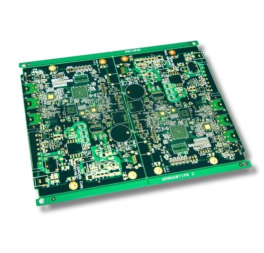
MedPCB manufactures Rogers 4003C PCBs for medical electronics that require low-loss RF performance, controlled impedance, and stable electrical characteristics.

• Dk of 3.38 +/- 0.05
• Dissipation factor of 0.0027 at 10 GHz
• Low Z-axis coefficient of thermal expansion at 46 ppm/°C
• ISO 13485 & IPC Class 2/3 PCB Manufacturing

Rogers 4003C for Medical PCBs
Certifications
Rogers 4350B Advantages on Medical PCB Manufacturing
introduction

What is Rogers 4003C for Medical PCB?

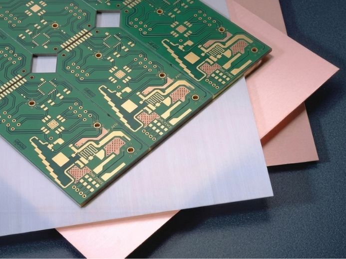
Rogers RO4003C is a hydrocarbon/ceramic laminate developed for high-frequency and RF circuit applications. Its controlled dielectric properties and low dissipation factor make it suitable for medical electronics that require stable signal transmission and controlled impedance.

Unlike PTFE-based microwave materials, RO4003C does not require special through-hole treatments. This simplifies PCB fabrication and handling while helping control manufacturing costs.

MedPCB manufactures RO4003C PCBs for prototype, low‑volume, and production applications, including multilayer and hybrid constructions. Our engineering team reviews key material, stackup, and impedance requirements before production to support reliable PCB performance in your medical device.

Quality

Rogers 4003C Advantages on Medical PCB Manufacturing

  • Multilayer PCB Compatibility
  • Low Dielectric Loss for High-Frequency Signals
  • Controlled Dielectric Constant for Impedance Stability
  • Excellent Dimensional and Thermal Stability
  • FR-4-Like Processing at Lower Fabrication Cost
Multilayer Compatibility
Rogers 4003C supports multilayer PCB construction for compact medical electronics. Its stable electrical properties help maintain signal integrity across multiple layers, which is important for imaging systems, monitoring devices, and other space-constrained medical equipment.
Low Dielectric Loss for High-Frequency Signals
Controlled Dielectric Constant for Impedance Stability
With a tightly controlled dielectric constant, Rogers 4003C enables precise impedance matching across the circuit. This stability reduces signal reflections and distortion, which is essential for preserving data clarity in high-speed and sensitive medical electronics.
Excellent Dimensional and Thermal Stability
Rogers 4003C exhibits low coefficients of thermal expansion (CTE) across a wide temperature range, ensuring high mechanical reliability under thermal stress. This stability helps prevent trace delamination or layer separation, ensuring long-term durability in critical medical devices subject to variable operational conditions.
FR-4-Like Processing at Lower Fabrication Cost
Rogers 4003C can be processed using standard FR-4 PCB manufacturing methods. This simplifies production and can lower fabrication costs. For medical electronics, this helps support reliable PCB production without adding unnecessary manufacturing complexity.
Why Choose Us

MedPCB as Rogers 4003C Medical PCB Partner

  • ISO 13485 Certified Halogen-Free PCB Production

    ISO 13485-Certified Medical PCB Manufacturing

    Our production follows ISO 13485, ISO 9001, and applicable IPC Class 2 and Class 3 requirements. Full traceability, revision control, inspection records, and controlled documentation help maintain consistent PCB quality.

  • Reliable Rogers 4003C Material Sourcing

    Reliable Rogers 4003C Material Sourcing

    We source genuine Rogers 4003C laminates directly from verified supply chains, ensuring consistent dielectric properties and batch-to-batch quality. This helps ensure that the specified laminate grade and key material properties are maintained from procurement through fabrication.

  • RO4003C Hybrid Stackup & Lamination

    RO4003C Hybrid Stackup & Lamination

    MedPCB manufacturing facility specializes in hybrid stackups, combining RO4003C high-frequency laminates with standard FR-4 layers to balance performance and cost-effectiveness. Precise temperature and pressure control during lamination prevents warping and guarantees registration accuracy for complex multilayer medical designs.

  • Free DFM Review Support

    Free DFM Review Support

    Our engineering team conducts thorough Design for Manufacturability (DFM) checks prior to production, identifying potential layout issues, trace bottlenecks, or layer stackup errors. This service minimizes revision cycles, reduces lead times, and ensures seamless production yields for critical medical applications.

  • Comprehensive Quality Assurance

    Comprehensive Quality Assurance

    We perform electrical testing, automated optical inspection (AOI), X-ray inspection, solderability testing, impedance testing, and microsection analysis. These tests help verify circuit continuity, solder joints, internal structures, and critical manufacturing dimensions for consistent PCB quality.

Specs

Technical Specifications

Technical Parameter

Manufacturing Capability


Order Quantity

≥ 1 PCS


Quality Grade

IPC-6012 Class 2 & Class 3


Board Size

Standard: up to 500 × 600 mm; Advanced: up to 1100 × 500 mm


Layer Count

1–40 layers. Standard: 1–20 layers; Advanced: 22–40 layers, including hybrid stackups


Board Thickness

0.2–10.0 mm. Standard: 0.2–3.2 mm; Advanced: 3.4–10.0 mm


Copper Thickness

17–350 μm (0.5–10 oz). Standard: 0.5–4 oz


Min. Trace Width / Spacing

Internal: 3/3 mil (0.075 mm). External: 3/3 mil advanced; 3.5/4 mil standard, depending on copper weight


Surface Finish

ENIG, ENEPIG, HASL Lead-Free, OSP, Immersion Silver, Immersion Tin, Flash Gold, Hard Gold, Soft Gold, and combination finishes


Impedance Tolerance

±5 Ω for <50 Ω; ±10% for ≥50 Ω


Quality Inspection

AOI, TDR impedance testing, Hi-Pot testing, X-Ray inspection, and microsection analysis


Compliance

ISO 13485, ISO 9001, RoHS, REACH, and IPC-6012

Get Instant Quote
Technical Specifications RO4003C
Capabilities

Rogers 4003C PCB Manufacturing Process on MedPCB

Step 1: Engineering Review & Stackup Planning

We review the Rogers 4003C PCB design for manufacturability, covering layer count, impedance requirements, material combination, trace geometry, dielectric thickness, drilling, and stack‑up. This early‑stage assessment helps identify potential issues so your design can be adjusted before production.

Step 2: Material Preparation & Inner-Layer Fabrication
Step 3: Lamination & Drilling
After lamination, we drill through-holes, blind vias, and other required features according to the PCB design. Drilling parameters are controlled to maintain hole accuracy and protect the Rogers 4003C material. Laser drilling can be used for microvias in HDI designs when required.
Step 4: Copper Plating & Outer Layer Fabrication
We plate the drilled holes to create reliable electrical connections between layers. The outer layers are then imaged, etched, and inspected to maintain the required trace width, spacing, and impedance. Controlled copper thickness helps support consistent high-frequency signal performance.
Step 5: Surface Finish & Final Inspection
We apply the specified surface finish, such as ENIG, ENEPIG, immersion silver, or immersion tin, based on the application and assembly requirements. Final inspection includes AOI, dimensional checks, electrical testing, and impedance verification when required. Each finished Rogers 4003C PCB is checked against the approved drawings and manufacturing specifications before shipment.
challenges

Challenges in Medical PCB Fabrication using Rogers 4003C

  • Controlled Impedance and Dielectric Thickness

    Controlled Impedance and Dielectric Thickness

    Challenge: Rogers 4003C PCBs require accurate dielectric thickness and trace geometry to maintain the target impedance. Small variations in these areas can affect signal integrity, especially in high-frequency medical electronics.

    Our Solution: We review the stackup, trace width, spacing, copper thickness, and dielectric thickness during DFM. Controlled fabrication processes and impedance testing help keep the finished PCB within the required impedance tolerance.

  • Hybrid Stackup Delamination

    Hybrid Stackup Delamination

    Challenge: Medical PCBs may combine Rogers 4003C with FR-4 in the same multilayer stackup. Differences in CTE and resin flow can create internal stress, warpage, or delamination during lamination.

    Our Solution: We check and control the stackup, material combination, lamination temperature, pressure, and cooling process. This helps maintain reliable layer bonding and reduce bow, twist, and delamination.

  • Copper Surface Roughness

    Copper Surface Roughness

    Challenge: Standard copper foil has a rougher surface that can increase signal loss at high frequencies. This becomes more important as operating frequencies increase, especially above 10 GHz.

    Our Solution: For high-frequency designs, we can recommend Rogers 4003C LoPro with low-profile copper. Its smoother copper surface helps reduce conductor loss and maintain signal integrity at higher frequencies.

  • Drilling and Hole-Wall Quality

    Drilling and Hole-Wall Quality

    Challenge: Rogers 4003C requires controlled drilling to maintain accurate hole dimensions and reliable plated through-holes. Poor drilling can cause rough hole walls, burrs, or weak copper plating.

    Our Solution: We control drill parameters based on the board thickness, hole size, and material construction. Hole-wall quality is inspected before copper plating to support reliable electrical connections and long-term PCB performance.

4003C Technical Specifications
Specs

Rogers 4003C Technical Specifications

The following table summarizes typical material properties. Actual values may vary based on laminate thickness, copper construction, test method, and specifications.

Property

Typical RO4003C Value

Dielectric Constant, εr (Process)

3.38 ± 0.05

Dielectric Constant, εr (Design)

3.55

Dissipation Factor, tan δ

0.0027 / 0.0021

Thermal Coefficient of εr

+40

Coefficient of Thermal Expansion

11 / 14 / 46

Tg

>280°C

Td

425°C

Thermal Conductivity

0.71 W/m·K

Moisture Absorption

0.06%

Copper Peel Strength

1.05 (6.0)

Flammability

N/A

Lead-Free Process Compatible

Yes


Need a Rogers 4003C PCB for your medical application? Send us your Gerber files and stackup requirements for a free DFM review.

Case Study

Rogers 4003C PCB Cases in Medical Equipments

  • MRI Machines
    MRI Machines PCB MRI Machines PCB

    MRI Machines

    MedPCB fabricated a 6 layer Rogers 4003C PCB with a controlled multilayer stack up and 1 oz copper to satisfy the customer’s performance specifications. The board underwent controlled lamination, precision drilling, copper plating, and ENIG surface finishing. Impedance testing and electrical inspection were completed before shipment.

  • X-Ray Machines 
    X-Ray Machines PCB X-Ray Machines 

    X-Ray Machines 

    The customer needed a multilayer PCB with stable high-frequency signal performance for an X-ray imaging system. This board was produced by MedPCB with controlled dielectric thickness, copper weight, and impedance. Precision drilling, plated-through holes, and ENIG finishing supported reliable connections and long-term operation. Each board passed AOI and electrical testing before shipment.

  • RF Generator Power Amplifier 
    RF Generator Power Amplifier PCB RF Generator Power Amplifier 

    RF Generator Power Amplifier 

    A medical equipment manufacturer needed a stable RF PCB for an ablation generator operating at high frequency. MedPCB manufactured a 4-layer Rogers 4003C PCB using controlled copper thickness and multilayer lamination. Precision drilling and plated-through-hole processing supported reliable interlayer connections. The completed boards passed AOI and electrical testing.

  • Mammography Machine 
    Mammography Machine PCB Mammography Machine 

    Mammography Machine 

    MedPCB fabricated this ultra-low-noise, high-density interconnect PCBs for high-resolution digital image detectors.Utilizing fine-line trace geometries, microvias, and a Rogers/FR-4 hybrid stack-up, we ensured minimal signal distortion and low thermal drift. The boards were finished with Electroless Nickel Immersion Gold (ENIG) and underwent flying probe testing along with X-ray inspection  to meet stringent IPC Class 3 medical standards.

Faqs

Frequently Asked Questions

Our Medical Rogers 4003C PCB FAQ addresses essential questions regarding your eco-friendly manufacturing requirements. We cover our capabilities for multilayer halogen-free circuits, material selection, thermal stability, strict ISO 13485 quality standards, and compliance with RoHS and REACH regulations. For every medical PCB project, we guarantee high-precision fabrication tailored for critical healthcare applications.

1. Can Rogers 4003C Be Processed Like Standard FR-4?
Yes. Rogers 4003C can use many standard FR-4 fabrication processes. This helps simplify manufacturing and control production costs.
2. Can Rogers 4003C Be Used in Hybrid Stackups?
Yes. Rogers 4003C can be combined with standard FR-4 cores or prepregs to create cost-effective hybrid PCB stackups, allowing high-frequency performance on critical signal layers while keeping total manufacturing costs down.
3. What Is the Difference Between RO4003C and RO4350B?
The main difference is that RO4350B is flame-retardant with a UL 94 V-0 rating, whereas RO4003C is non-brominated and does not carry a UL 94 V-0 rating. Additionally, RO4003C offers a lower dissipation factor and lower dielectric constant, making it slightly better for signal loss in non-V-0 applications.
4. What Is The Best Surface Finish For Rogers 4003C PCBs?
ENIG is commonly used. For higher-frequency RF designs, Immersion Silver or OSP may be preferred to reduce signal loss.
5. What Is The Typical Lead Time For Rogers 4003C Prototypes?
Prototype lead time depends on board complexity and material availability. Standard prototypes can be produced faster when the required Rogers 4003C material is in stock.
6. Can Rogers 4003C Withstand Lead-Free Soldering Temperatures?
Yes. Rogers 4003C can withstand lead-free reflow temperatures up to 260°C when the assembly profile is properly controlled.
7. Does Rogers 4003C Meet UL 94 V-0?
No. Rogers 4003C is non-brominated and does not have a UL 94 V-0 rating. If V-0 is required, MedPCB can recommend a suitable alternative during DFM review.
8. Is Rogers 4003C Cost-Effective For High-Volume PCB Production?
Yes. Its FR-4-like processing and competitive material cost make Rogers 4003C suitable for cost-sensitive, high-volume medical PCB production.
9. Can Rogers 4003C Handle Demanding Medical Environments?
Yes. Rogers 4003C provides stable electrical and thermal performance for demanding high-frequency applications. Proper stackup and manufacturing controls are still required for harsh operating conditions.
10. How Does Rogers 4003C Compare with Standard FR-4?
Rogers 4003C has lower dielectric loss and more stable high-frequency performance than conventional FR-4. It is better suited for medical PCBs that require controlled impedance and reliable RF signal transmission.

Product Related