Medical Metal Core PCB

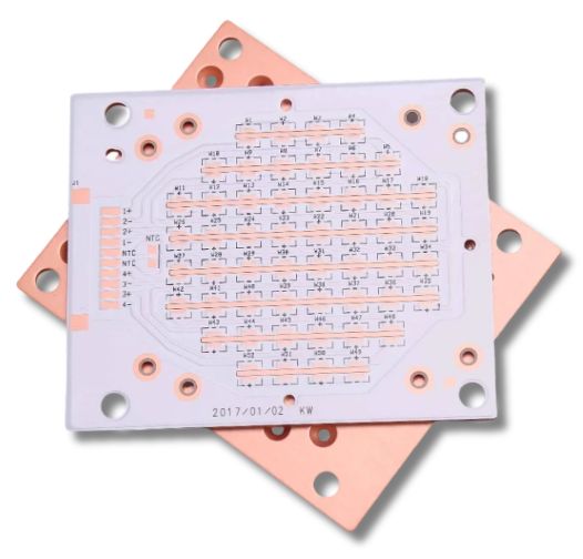
We fabricate Metal Core PCBs for superior thermal management in high-power medical devices. Our advanced substrate processing and certified quality standards ensure rapid heat dissipation and maximum precision for life-critical devices.

• ISO 13485 & IPC Class 2/3 Compliant
• Aluminum and Copper Core PCB Options
• Thermal Conductivity up to 5.0 W/m·K
• Single-Sided, Double-Sided, and Selected Multilayer Structures

Medical Metal Core PCB
Certifications
What is Medical Metal Core PCB
introduction

What is Medical Metal Core PCB?

A medical metal core PCB uses aluminum or copper as a base instead of FR4. It draws intense heat away from critical electronic components. In multilayer configurations, the metal core balances heat dissipation across both sides of the board. By transferring thermal energy directly to a heatsink core, these boards prevent overheating and component failure. This advanced thermal stability is essential for high-power medical equipment, ensuring total operational reliability and long-term durability in life-critical devices.

Products

Advantages of Medical Metal Core PCB

  • Superior Heat Dissipation
  • Higher Current-Carrying Capacity
  • Enhanced Mechanical Strength
  • Reduced Reliance on Bulky Hardware
Superior Heat Dissipation
With thermal conductivity ratings up to 5.0 W/m·K, our MCPCBs rapidly draw heat away from high-power components. By maintaining low operating temperatures, they protect sensitive electronics and extend device operational lifespan.
Higher Current-Carrying Capacity
Enhanced Mechanical Strength
Reduced Reliance on Bulky Hardware
Why Choose Us

Choosing MedPCB as Medical Metal Core PCB Partner

  • ISO 13485 Certified Manufacturing

    ISO 13485 Certified & Medical-Grade Quality

    Our production facilities operate under strict ISO 13485, ISO 9001, and IPC Class 2/3 medical standards. We maintain complete regulatory compliance to ensure every metal core PCB delivers the ultra-high reliability required for life-critical healthcare applications.

  • Advanced Metal Substrate Options

    Advanced Metal Substrate Options

    We support a broad range of high-performance metal bases, including aluminum and copper substrates. This flexibility allows us to tailor mechanical strength, weight, and thermal performance to your exact medical device specifications.

  • Superior Heat Dissipation up to 5.0 W/m·K

    Superior Heat Dissipation up to 5.0 W/m·K

    Our MCPCBs feature thermal conductivity ratings up to 5.0 W/m·K, bonding directly with internal metallic heatsinks. This high-efficiency heat transfer keeps sensitive electronics cool and prevents thermal degradation in high-power clinical devices.

  • Large PCB 1500mm x 600mm Fabrication

    Large PCB 1500mm x 600mm Fabrication

    With maximum panel size capabilities up to 1500mm x 600mm, we manufacture large-scale metal core circuit boards for complex diagnostic imaging systems, surgical lighting rigs, and heavy-duty medical power equipment.

  • Cost-Effective Metal Core Manufacturing

    Cost-Effective Metal Core Manufacturing

    By leveraging streamlined substrate processing and optimized manufacturing workflows, we deliver high-quality MCPCBs at highly competitive prices helping you achieve superior thermal performance within budget.

  • Engineering & DFM Support

    Engineering & DFM Support

    MedPCB provides thorough Design for Manufacturability (DFM) reviews to identify potential production issues early. We collaborate directly with your team to optimize trace routing, dielectric layer selection, and thermal vias to streamline production cycles, improve yield rates, and accelerate time to market.

Specs

Technical Specifications

Feature / Parameter

Specification

Layer Count

Single-layer, Double-layer, 4-layer Aluminum PCB

Thermal Conductivity

Up to 5 W/m·K

Board Thickness

0.3 mm – 5.0 mm

Copper Thickness

35 µm – 240 µm

Maximum Board Size

1500 mm × 600 mm

Minimum Board Size

5 mm × 5 mm

Min. Line Width / Spacing

0.1 mm

Surface Finish

Lead-Free HASL, ENIG (Chemical Nickel/Gold), Chemical Tin, Chemical Silver, OSP

Board Warpage

≤ 0.5% (Thickness: 1.6 mm, Size: 300 mm × 300 mm)

Finished Size Tolerance

±0.15 mm

V-Cut Score Tolerance

±0.1 mm

Hole Position Tolerance

±0.076 mm


Technical Specifications Metal Core PCB
Capabilities

MedPCB Medical Metal Core PCB Process

Step 1: Substrate Preparation & Cleaning
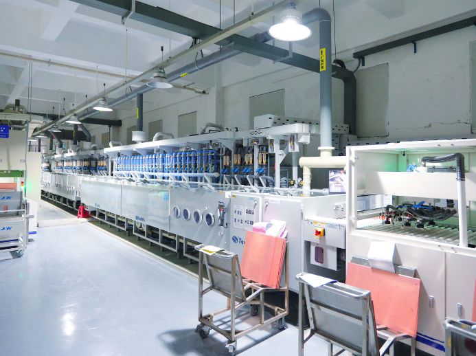
The manufacturing process begins by preparing aluminum or copper metal bases to the required panel size. The metal base is cleaned and treated to remove surface contaminants and improve bonding with the dielectric layer.
Step 2: Dielectric & Copper Lamination
Step 3: Circuit Imaging & Etching
Step 4: Precision Drilling & Profiling
Step 5: Solder Mask, Silkscreen & Surface Finishing
Quality Control

Common Challenges in Medical Metal Core PCB Manufacturing

  • Material Cost & Weight Optimization

    Material Cost & Weight Optimization

    Challenge: Metal core substrates like copper bases carry higher raw material costs and add significant physical weight compared to standard FR-4 boards, which can strain budget-conscious or lightweight device designs.

    Our Solution: We have in-stock material selection for high-conductivity aluminum with optimized board geometries to deliver medical-grade heat management while keeping weight and production costs strictly controlled.

  • Process Complexity & Metal Base Machining

    Process Complexity & Metal Base Machining

    Challenge: Fabricating MCPCBs requires complex multi-stage laminations under extreme heat and pressure, as well as heavy-duty drilling through tough metal cores that wear down standard tooling.

    Our Solution: Using specialized, carbide-tipped machining tools and automated lamination presses, we precisely drill and profile metal substrates without burrs, mechanical stress, or structural layer separation.

  • Dielectric Layer Integrity & Thermal Hot Spots

    Dielectric Layer Integrity & Thermal Hot Spots

    Challenge: Micro-voids or microscopic defects within the insulating dielectric layer disrupt thermal flow, creating localized hot spots that can destroy sensitive medical components or cause total board failure.

    Our Solution: We utilize high-integrity thermal dielectric materials and perform automated optical and thermal-imaging inspections to ensure uniform heat transfer and avoid dielectric voids across every panel. 

  • Thermal Cycling & Joint Fatigue

    Thermal Cycling & Joint Fatigue

    Challenge: Frequent power spikes and temperature swings cause uneven expansion between the metal base and surface components, risking solder joint fatigue, trace lifting, and eventual open circuits.

    Our Solution: We'll help you choose suitable dielectric materials based on your project needs and control bonding and manufacturing parameters to improve thermal-cycle reliability.

Metal Core PCB Materials Supported by PCBMay 
Specs

Metal Core PCB Materials Supported by MedPCB 

MedPCB supports high-performance Metal Core PCB (MCPCB) materials designed for high thermal conductivity, superior heat dissipation, and long-term reliability in critical medical devices.

Aluminum Core PCB – Aluminum is the most popular metal core material, offering excellent thermal dissipation, high strength, and cost-efficiency. It works well for medical equipment requiring reliable cooling, such as high-power LED lighting, power supplies, and surgical lamps.

Copper Core PCB – Due to its superior thermal conductivity over aluminum, copper excels in demanding thermal environments. It can be considered for high-power medical electronics such as laser systems and imaging equipment where efficient heat dissipation is required.

MedPCB supports metal core board fabrication based on your thermal management needs, component density, and device size. Send your files to us so we can review your design through a free DFM check for reliable medical PCB production.

Case Study

Medical Metal Core PCB Cases

  • Ceiling-Mounted Surgical Light Towers 
    Ceiling-Mounted Surgical Light Towers PCB Ceiling-Mounted Surgical Light Towers 

    Ceiling-Mounted Surgical Light Towers 

    High-output, multi-head LED systems use aluminum substrates to transfer heat away from LEDs during long surgical procedures. Efficient heat dissipation helps maintain consistent brightness and reduces LED temperature buildup.

  • Endoscopic Headlamps 
    Endoscopic Headlamps PCB Endoscopic Headlamps 

    Endoscopic Headlamps 

    Lightweight headlamps benefit from aluminum substrates because they support efficient thermal management in a compact PCB design. Better heat transfer helps prevent excessive surface temperatures near the surgeon and patient.

  • Overhead Neonatal Phototherapy Units 
    Overhead Neonatal Phototherapy Units PCB Overhead Neonatal Phototherapy Units 

    Overhead Neonatal Phototherapy Units 

    These systems use high-intensity blue LEDs that may operate for extended periods. Aluminum substrates help dissipate LED heat efficiently, supporting stable light output and reliable operation.

  • Dental Illuminators 
    Dental Illuminators PCB Dental Illuminators 

    Dental Illuminators 

    Aluminum substrates help manage heat in compact, high-CRI dental lighting systems. Efficient thermal transfer reduces heat accumulation around the LEDs while helping maintain consistent illumination during procedures.

Faqs

Frequently Asked Questions

Our Medical Metal Core PCB FAQ addresses essential questions regarding your manufacturing requirements. We cover our capabilities for complex medical electronics, supply chain management, assembly timelines, rigorous quality inspection protocols, and our capacity to scale from initial builds to production batches. For every medical device project, we guarantee precision-focused, medical-grade assembly standards.

1. How Does a Metal Core PCB Compare With an FR-4 PCB?
Metal Core PCBs has better heat dissipation than FR-4 PCBs. They are better suited for medical devices with high-power components or continuous thermal loads.
2. How Do Aluminum Core and Copper Core PCBs Differ?
Aluminum cores are lightweight, cost-effective, and provide good thermal performance. Copper cores provide better thermal conductivity but add more weight and cost.
3. Can Metal Core PCBs Support Through-Hole Components?
Yes. Through-hole components can be used, but the holes must be electrically isolated from the metal core to prevent short circuits. Surface-mount components are often preferred for better heat transfer.
4. How Do I Determine The Thermal Conductivity Needed for a Medical Metal Core PCB?
Start with the component’s power dissipation and maximum operating temperature. Thermal simulation can help determine the required thermal performance for your medical device.
5. What is The Lead Time for Medical Metal Core PCB prototypes?
Standard prototypes typically take 5–10 business days. Copper-core and high-conductivity designs may require 2–3 weeks, depending on the design and material requirements.
6. Can Medical Metal Core PCBs Support High-Power Applications?
Yes. They are suitable for medical devices that generate significant heat. The metal core helps transfer heat away from high-power components and maintain stable operating temperatures.
7. Are Medical Metal Core PCBs Suitable For Multilayer Designs?
Yes. Most designs use one or two copper layers, but multilayer structures can be developed when your medical application requires more routing space or circuit density.
8. How does MedPCB Ensure Quality in Medical Metal Core PCB Manufacturing?
MedPCB uses controlled drilling, lamination, plating, and surface finishing processes. Each board can be inspected for thermal performance, electrical reliability, dimensional accuracy, and mechanical quality.

Product Related