Rogers TC350 PCB for Medical Devices

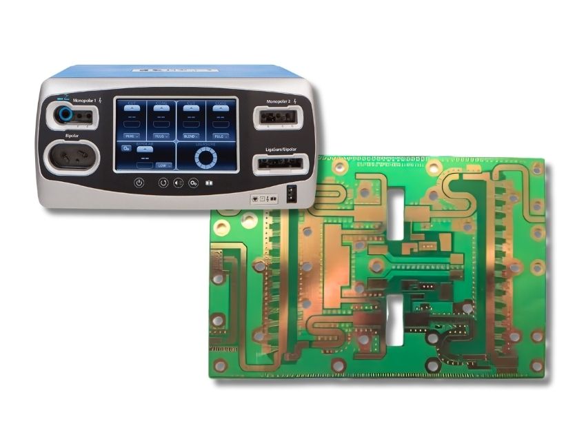
MedPCB manufactures Rogers TC350 PCBs for medical RF and high-power electronics. Using ceramic-filled PTFE laminate, we deliver controlled-impedance circuits under ISO 13485-compliant quality management.

• Rogers TC350 Ceramic-Filled PTFE Laminates 
• Dk 3.50 ± 0.05 & Df 0.0020 @ 10 GHz 
• 0.72 W/m·K Thermal Conductivity for High-Power RF Circuits 
• ISO 13485 & IPC Class 2/3 Manufacturing

Rogers TC350 PCB for Medical Devices
Certifications
What Is a TC350 PCB?
introduction

What Is a TC350 PCB?

Rogers TC350 is a ceramic-filled, PTFE-based laminate reinforced with woven glass for high-frequency PCB applications. It combines a dielectric constant of 3.50 ± 0.05, a dissipation factor of 0.0020 at 10 GHz, and thermal conductivity of 0.72 W/m·K.

These characteristics support you with reliable high-frequency signal performance and effective heat dissipation. It is well-suited for medical RF hardware such as imaging systems and RF surgical equipment.

MedPCB produces custom Rogers TC350 PCBs for medical RF and high-power electronics, including multilayer and hybrid stack-up projects.

Properties

Key Advantages of Medical-Grade TC350 PCBs

  • High Thermal Conductivity for Heat Dissipation
  • Stable Dielectric Constant for Consistent RF Performance
  • Low Loss for High-Frequency RF Circuits
  • Low CTE for Reliable Plated Through-Holes
High Thermal Conductivity for Heat Dissipation
Medical RF power stages, including ablation generators, diathermy outputs, and MRI amplifier modules, concentrate significant heat in small areas. With thermal conductivity of 0.72 W/m·K, TC350 delivers superior heat dissipation compared to standard unfilled PTFE-based microwave laminates. This material spreads heat away from hot power transistors and printed inductors, helping to lower junction temperatures and extend component life.
Stable Dielectric Constant for Consistent RF Performance
Low Loss for High-Frequency RF Circuits
Low CTE for Reliable Plated Through-Holes
Why Choose Us

Why Choose MedPCB?

  • ISO 13485 Certified TC350 PCB Production

    ISO 13485 Certified TC350 PCB Production

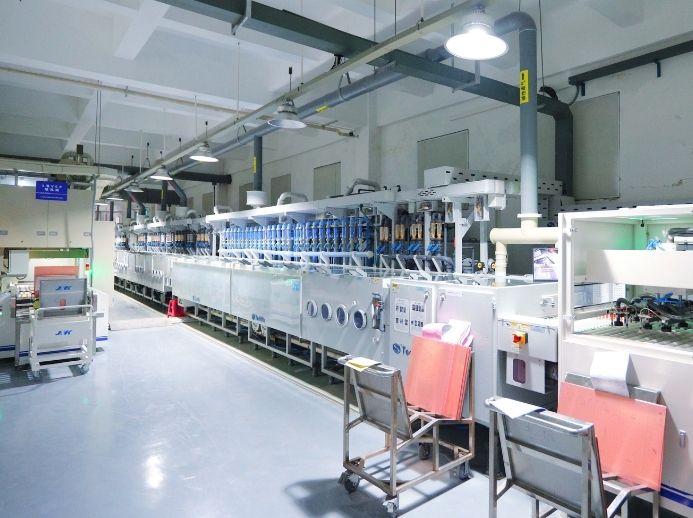
    MedPCB manufactures TC350 PCBs under an ISO 13485 quality management system. Controlled production, material records, and process documentation support consistent quality and traceability for medical PCB projects.

  • Free DFM Review with RF Stackup & Material Consultation

    Free DFM Review with RF Stackup & Material Consultation

    Before your order enters production, our engineers perform a free DFM review of your TC350 RF design files. The review covers impedance calculations based on your stackup, trace/space verification, copper balance analysis, and PTFE-specific routing checks.

  • Rogers TC350 Material Sourcing

    Rogers TC350 Material Sourcing

    MedPCB sources genuine Rogers TC350 laminates through established supplier channels. Every incoming material undergoes IQC verification of specifications and supporting documentation prior to production. This helps you maintain consistent electrical and manufacturing performance for your medical-device projects.

  • Advanced Hybrid Multilayer Capability with PTFE Laminates

    Advanced Hybrid Multilayer Capability with PTFE Laminates

    Our engineers support hybrid PCB builds combining Rogers TC350 RF layers with FR-4 or other compatible laminates. We review your stack-up layout, material selection, and lamination parameters to handle differences in thermal and mechanical properties between dissimilar materials.

  • Quality Control, Testing & Material Traceability

    Quality Control, Testing & Material Traceability

    We perform AOI, X-ray inspection, microsection analysis, impedance testing, electrical testing, according to your project requirements. Full-batch material records and production documentation are preserved to support complete traceability for your medical-device projects.

Specs

Technical Specifications

Capability Standard Advanced
PCB Type RF, multilayer, hybrid, HDI RF, multilayer, hybrid, HDI
Layer count 1-20 layers 22-40 layers
Minimum trace/space 4/4 mil 3/3 mil (internal, 1/2 oz base copper)
Minimum via (mechanical) 0.20 mm (8 mil) 0.20 mm (8 mil)
Laser via 0.10-0.15 mm (4-6 mil) 0.10-0.15 mm (4-6 mil)
Maximum aspect ratio 10:1 20:1
PTH wall thickness 20 µm (0.8 mil) 25 µm (1 mil)
Finished copper 1/2-4 oz 1/3-10 oz
Finished board thickness 0.2-3.2 mm 3.4-10 mm
Maximum board size 500 × 600 mm 1100 × 500 mm
Impedance control ±10% (≥50 Ω); ±5 Ω (<50 Ω) ±10% (≥50 Ω); ±5 Ω (<50 Ω)
Surface finishes ENIG, ENEPIG, immersion silver, immersion tin, lead-free HASL, OSP, hard gold, soft gold, flash gold ENIG+OSP, ENIG+Gold finger, immersion silver+Gold finger combinations
Medical TC350 PCB
Process

Our Medical TC350 PCB Production Process

Step 1: Engineering Review & RF Stackup Verification
Every TC350 PCB order begins with our engineering team reviewing your Gerber files, stackup drawing, and impedance requirements. We verify Dk assumptions, calculate trace widths for 50 Ω (or custom targets) using field solvers, and flag PTFE-specific DFM risks before material is released.
Step 2: PTFE Material Preparation & Inner Layer Fabrication
Step 3: Lamination, Drilling & Plated Through-Hole Processing
Step 4: Outer Layer Fabrication & Surface Finish
Step 5: Electrical Testing & Final Inspection
Quality Control

Common Challenges in Medical TC350 PCB Manufacturing

  • Material Selection & Handling

    Material Selection & Handling

    An unverified or substituted laminate can fail Dk/Df verification and compromise RF qualification.

    Our Solution: MedPCB maintains controlled storage for ceramic-filled PTFE, tracks every lot to its certificate of conformance, and verifies Dk/Df against the Rogers TC350 datasheet before cutting.

  • Thermal Management

    Thermal Management

    High-power medical RF circuits can concentrate heat in compact areas, making thermal design and heat spreading important for reliable operation.

    Our Solution: During DFM review, we evaluate thermal requirements and recommend suitable PCB construction options, including heavy copper, copper coins, thermal via arrays, and busbar integration where applicable. These approaches help improve heat spreading and current-carrying capability in your high-power medical PCB projects.

  • PTFE-Based Fabrication

    PTFE-Based Fabrication

    PTFE is soft, hydrophobic, and dimensionally sensitive, which can make drilling, surface treatment, and plating more demanding than conventional FR-4 fabrication.

    Our Solution: MedPCB uses controlled PTFE-compatible surface finish and metallization processes to promote reliable copper adhesion and plated-through-hole performance.

  • RF Signal Integrity

    RF Signal Integrity

    Even slight over-etch shifts impedance and degrades return loss on high-frequency lines.

    Our Solution: MedPCB controls etch processes tightly, places impedance coupons on every panel, and verifies lines to ±10% (for 50 Ω and above) or ±5 Ω (below 50 Ω) by TDR, with solder mask skip zones over RF traces where specified.

Rogers TC350 Material Specifications
Specifications

Rogers TC350 Material Specifications

Rogers TC350 is a ceramic-filled PTFE laminate designed for high-frequency applications where stable dielectric performance, low RF loss, and thermal management are important. These properties make it suitable for medical RF equipment such as MRI systems, RF ablation devices, and diathermy equipment.

Property Rogers TC350
Dielectric Constant (Dk) 3.50 ± 0.05
Dissipation Factor (Df) 0.0020 @ 10 GHz
Thermal Conductivity 0.72 W/m·K
Thermal Coefficient of Dk -9 ppm/°C
CTE, X / Y / Z 7 / 7 / 23 ppm/°C
Water Absorption 0.05%
Flammability UL 94 V-0
Lead-Free Process Compatible Yes

Need a Rogers TC350 PCB for your medical device? Send us your Gerber files for a free DFM review and quote.

industries

Applications of Medical TC350 PCBs

More Industries

Case Study

Medical TC350 PCB Case Studies

  • TC350 RF Power Amplifier Board for MRI Coil Driver
    TC350 RF Power Amplifier Board for MRI Coil Driver TC350 RF Power Amplifier Board for MRI Coil Driver

    TC350 RF Power Amplifier Board for MRI Coil Driver

    For this customer’s MRI coil-driver project, stable impedance performance and reliable thermal capability were required. We produced 4-layer TC350 PCBs with 6oz outer copper and ENIG finish, plus thermal via arrays for enhanced heat dissipation. All panels passed TDR impedance check, 100% electrical test and microsection inspection before shipment.

  • TC350 High-Frequency Generator PCB for RF Ablation System
    TC350 High-Frequency Generator PCB for RF Ablation System TC350 High-Frequency Generator PCB for RF Ablation System

    TC350 High-Frequency Generator PCB for RF Ablation System

    A customer's RF ablation generator build required reliable high-voltage operation and patient-contact safety. We produced two-layer 0.030" TC350 boards with 3 oz finished copper and an immersion silver finish, plus documented clearance verification. All panels passed 100% electrical test and inspection per IPC-A-600 before shipment.

  • TC350 Plus Hybrid Multilayer for Microwave Diathermy Device
    TC350 Plus Hybrid Multilayer for Microwave Diathermy Device TC350 Plus Hybrid Multilayer for Microwave Diathermy Device

    TC350 Plus Hybrid Multilayer for Microwave Diathermy Device

    This customer project needed halogen-free materials for a microwave diathermy device, with RF and digital circuitry in a single stack. We produced 6-layer hybrid boards combining TC350 Plus RF layers with FR-4 digital layers, bonded with low-flow high-frequency prepregs and staged lamination. All panels passed 100% electrical test and microsection inspection before shipment.

  • Impedance-Controlled TC350 PCB for Wireless Patient Telemetry Module
    Impedance-Controlled TC350 PCB for Wireless Patient Telemetry Module Impedance-Controlled TC350 PCB for Wireless Patient Telemetry Module

    Impedance-Controlled TC350 PCB for Wireless Patient Telemetry Module

    A customer's patient telemetry module build called for compact controlled-impedance traces with reliable RF performance. We produced TC350 boards on 0.010" laminate with 4/4 mil traces, with solder mask omitted over RF circuits. All panels passed TDR impedance check and 100% electrical test, with impedance reports archived under ISO 13485 documentation requirements.

Faqs

Frequently Asked Questions

Our Medical TC350 PCB FAQ addresses key questions regarding Rogers TC350 ceramic-filled PTFE laminate properties and fabrication standards. We cover thermal conductivity (0.72 W/m·K), low loss tangent, dielectric stability, hybrid FR-4 lamination, lead-free reflow compatibility, surface finishes, and DFM support. For every medical TC350 PCB project, we guarantee high-precision bare board manufacturing engineered for critical healthcare applications.

1. What Is the Difference Between TC350 and TC350 Plus?
Rogers TC350 and TC350 Plus are similar ceramic-filled PTFE laminates for high-frequency circuits. TC350 Plus delivers higher thermal conductivity and lower dissipation factor for higher-power requirements. Both material families offer halogen-free variants. MedPCB fabricates both material options for your medical-device projects.
2. Why Is Thermal Conductivity Important in Medical RF PCBs?
RF power stages concentrate heat in small areas, and excess temperature shifts Dk, drifts tuning, and shortens component life. TC350's 0.72 W/m·K, roughly three times unfilled PTFE, spreads that heat effectively, lowering junction temperatures and keeping performance stable.
3. Can TC350 Be Combined with FR-4 in Hybrid Multilayer PCBs?
Yes. PCBMay routinely builds hybrid stacks with TC350 RF cores bonded to FR-4 layers using low-flow high-frequency prepregs. CTE mismatch is managed through lamination profiles, copper balance, and layer sequencing.
4. What Surface Finishes Are Recommended for TC350 PCBs?
ENIG and ENEPIG are the medical defaults, offering excellent shelf life, flat pads, and wire-bonding compatibility. Immersion silver offers the lowest RF loss and is preferred for pure microwave circuitry. Immersion tin and lead-free HASL are available alternates.
5. How Many Layers Can a TC350 Medical PCB Support?
PCBMay manufactures TC350 boards from 1 to 20 layers as standard and up to 40 layers advanced, including hybrid TC350/FR-4 constructions.
6. What Is the Minimum Trace Width and Spacing on TC350 PCBs?
Minimum trace/space is 4/4 mil standard and 3/3 mil advanced for internal layers at 1/2 oz base copper, including impedance-controlled lines verified by TDR. External layers start at 3.9/4.5 mil standard. Your DFM review will confirm achievable trace/space against copper weight and layer count.
7. Do You Provide Impedance Test Coupons for TC350 PCBs?
Yes. Every panel includes dedicated impedance coupons tested by TDR, with measured values reported against your targets (±10% for 50 Ω and above, ±5 Ω below 50 Ω). Reports are archived and shipped with your lot documentation.
8. Is TC350 Compatible with Lead-Free PCB Assembly?
Yes. TC350 is rated lead-free process compatible: decomposition temperature is 520 °C (initial) and 567 °C at 5% weight loss, and time to delamination exceeds 60 minutes at T260, T288, and T300, far beyond lead-free reflow peaks of about 260 °C.
9. Is Rogers TC350 UL 94 Rated?
Yes. TC350 is UL 94 V-0 rated, satisfying flammability requirements common to medical electronic devices.

Product Related