

Rigid-Flex PCBs in Medical Devices: Applications & Manufacturing
-

-
August 23, 2026


Rigid-flex PCBs power today’s most advanced wearables, implants, and surgical tools by folding complex electronics into tight, wire-free enclosures. Navigating material selection, rigorous testing, and vendor audits is critical to building a compliant product.

By eliminating bulky cables and connectors, this hybrid construction drastically shrinks package size while maximizing long-term reliability. Medical device designers choose rigid-flex construction for several practical reasons:
Rigid-flex lets you fold electronics into three-dimensional shapes, so devices shrink without losing capability. A compact medical PCB layout frees room for batteries and sensors. Patients receive lighter, more comfortable miniature medical electronics.
Connectors and cables can introduce additional mechanical and electrical failure points, especially in compact or frequently flexed medical devices. Rigid-flex medical PCB designs replace those links with integrated flex sections. You remove mating points, solder joints, and wiring errors.
Rigid-flex construction can combine multiple rigid sections and flexible interconnects into one PCB assembly, reducing the number of separate boards, cables, and connectors. This can simplify mechanical integration and reduce assembly interfaces.
Flexible sections can accommodate controlled bending, vibration, and mechanical movement more effectively than rigid interconnects when the flex structure is properly designed. Proper flex construction can improve mechanical reliability in applications involving repeated movement or constrained packaging.
Direct flex interconnects keep signal paths short and low-noise. Controlled impedance flex layers support high-speed data and medical telemetry PCB needs. Clean routing preserves analog sensor signals.
Rigid-flex boards bend to follow the human body and fit non-standard enclosures. 3D packaging medical PCB techniques fold circuits around curved housings, endoscope heads, and capsule-sized tools.
Polyimide delivers strong thermal and chemical resistance, yet the full rigid-flex assembly must be assessed for your exact sterilization method, including temperature, pressure, cycle count, and exposure duration. Validate materials and stack-up against target sterilization cycles prior to production.
Rigid-flex technology appears across nearly every class of medical electronics. Implants, wearables, imaging, surgical tools, and drug delivery all benefit. Flex-rigid circuit boards for healthcare meet unique demands in each application.
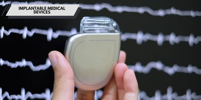
Pacemakers, neurostimulators, and cochlear implants rely on implantable rigid-flex PCB construction. Flex sections let a pacemaker circuit board conform to anatomy and absorb body movement. Miniaturization directly improves patient comfort and recovery.
A wearable medical PCB must bend with the body all day without failing. ECG patches, glucose monitors, and patient monitoring equipment PCB designs track vitals continuously. Biosensor rigid-flex PCB layouts keep electrodes close to the skin.
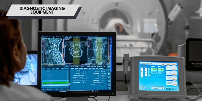
Rigid-flex PCBs can be useful in compact diagnostic modules, imaging probes, and assemblies where electronics must fit into constrained or moving structures. Controlled impedance and well-managed signal paths can help maintain signal integrity in high-speed or low-level signal applications.
Surgical robots need boards that bend inside articulated arms and instrument tips. A surgical robotics PCB carries power, sensors, and control signals through moving joints. This reliability supports precise, tremor-free motion.
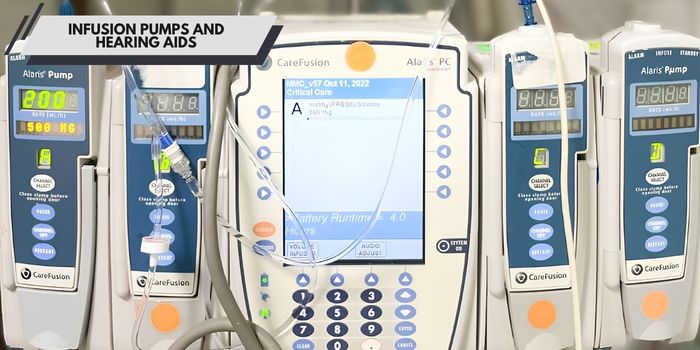
Infusion pumps need durable, serviceable electronics that fit beside fluidics. Hearing aids represent the extreme of micro-PCBA medical design, integrating amplifiers into compact housings. You simplify final assembly in both product families.
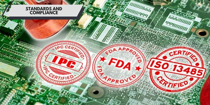
Medical electronics sit under three separate sets of requirements: device safety regulations, PCB manufacturing standards, and quality system standards. You must satisfy all three. Knowing which document applies to whom prevents costly audit findings.
IEC 60601 governs the safety and essential performance of medical electrical equipment. It applies to your finished device, not the bare board. Your fabricator supports you with accurate material data and consistent construction.
IPC-6013 sets the performance specification for flex and rigid-flex boards. IPC-A-600 defines what inspectors accept visually. IPC Class 3 medical PCB standards demand the tightest tolerances for high-reliability builds.
ISO 13485 is the quality management system standard for medical device manufacturers. It requires traceability, risk management, and documented process control. An ISO 13485 medical PCB program means your fabricator supports your QMS with batch records.
The FDA requires design controls for your device under 21 CFR Part 820, now aligned with ISO 13485 through the QMSR. 510(k) and PMA describe clearance pathways, not PCB requirements. Your fabricator contributes controlled drawings, process data, and first article reports.
RoHS and REACH restrict hazardous substances in materials sold into Europe. ISO 10993 evaluates the biological safety of materials that contact patients. For implantable or patient-contacting applications, material selection may also need to support the device manufacturer’s biological evaluation under the applicable ISO 10993 requirements. PCB material compatibility should be assessed as part of the finished device and its intended contact conditions.
Rigid-flex design rewards discipline. Bend geometry, via placement, and stackup choices decide whether your board survives production and service. Work these details early with your fabricator to avoid rework.
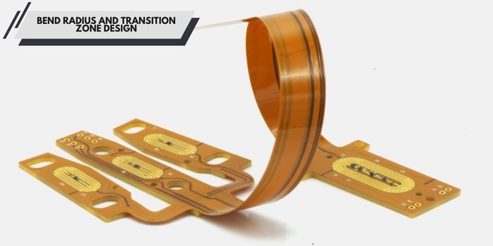
Your flex sections need a bend radius large enough to avoid cracking copper. Ten times the flex layer thickness serves as a common starting rule. Dynamic flex PCB medical devices that bend repeatedly during use need larger radii.
Keep vias away from bend areas and transition zones. Plated copper concentrates stress and cracks under repeated flexing. Stiffeners and edge beads reinforce the flex-rigid transition zone.
High-speed medical channels need controlled impedance on every flex layer. Return paths must stay continuous across rigid-flex boundaries. Broken reference planes degrade high-speed and RF telemetry medical PCB performance.
Compact medical electronics emit and receive interference easily. You manage EMI with solid reference planes, short flex runs, and shielding films. Sensitive analog front ends need isolation from switching converters.
Power stages in medical devices concentrate heat on rigid sections. You spread heat with copper pours, thermal vias, and heatsinks. Flex layers conduct poorly, so route high-power nets through rigid cores.
DFM means designing boards your fabricator can build repeatably. You follow laminate availability, minimum drill sizes, and adhesive squeeze tolerances. Early DFM input prevents defects and delays.
Material selection drives everything in medical builds: flexibility, sterilization survival, signal performance, and biocompatibility. Polyimide dominates flex layers, while FR-4 and high-performance laminates carry rigid sections.
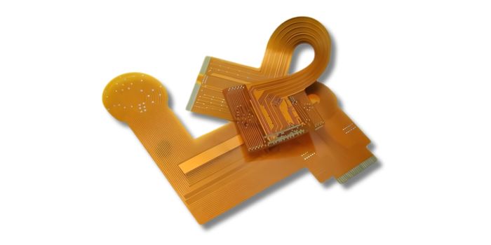
Polyimide flexible PCB medical construction tolerates heat, chemicals, and repeated flexing. FR-4 works well for rigid sections but cracks when bent. Select each laminate for its intended function.
Adhesiveless polyimide laminates remove the acrylic bond line that fails under heat and flexing. They support tighter bends and thinner profiles. Coverlays protect flex traces because solder mask cracks when flexed.
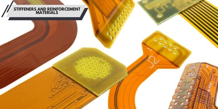
Stiffeners brace flex tails and connector areas. You can choose polyimide, FR-4, or metal stiffeners depending on thickness and rigidity needs. Specify stiffener placement precisely in your drawings.
ENIG and ENEPIG dominate medical boards for flatness and fine-pitch reliability. ENEPIG adds a palladium layer that supports soldering and gold wire bonding. Immersion silver supports RF performance where the nickel layer under gold adds signal loss.
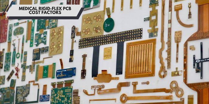
Medical rigid-flex boards cost more than standard rigid boards because of materials, processes, and verification. Knowing what drives price helps you budget and trim waste.
Each additional rigid or flex layer adds material and lamination cycles. HDI rigid-flex medical PCB construction with microvias costs more than conventional through holes. Simplify stackups where you can.
Adhesiveless polyimide costs more than adhesive-based flex materials. ENIG and ENEPIG finishes price above HASL and OSP. Low-cost materials compromise long-term reliability, so budget accordingly.
Laser microvias, buried vias, and via filling add process steps and cost. Tight bend fabrication and precise coverlay alignment demand skilled handling. Advanced processes provide reliability that general-purpose manufacturers cannot match.
Class 3 builds require full electrical test, impedance coupons, and microsection analysis. Cleanroom PCB assembly and inspection add cost but protect patient safety. Include these requirements in the initial quote, not after the prototype.
Prototypes carry heavy tooling and setup charges spread over a few boards. Production volumes amortize tooling, fixtures, and engineering across thousands of units. Ask your fabricator about NPI pricing that scales.
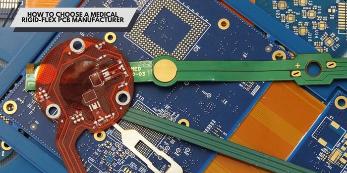
Your manufacturer becomes a regulated supply chain partner, not just a company. Audit them like you audit your own processes. These checks separate qualified medical device electronics contract manufacturing partners from general manufacturers.
Request current copies of ISO 9001, ISO 14001, UL, and RoHS certificates. Medical equipment PCB fabrication often requires specific UL recognition. Third-party audit reports add confidence.
Confirm layer counts, minimum trace widths, and flex layer counts match your design. Check their experience with HDI rigid-flex medical PCB stackups. A capability mismatch forces the redesign you want to avoid.
A good fabricator reviews your Gerbers before quoting and identifies bend, via, and material risks. Free DFM feedback demonstrates engineering capability. Early feedback prevents costly late-stage changes.
Ask how they inspect finished boards: AOI, X-ray, flying probe, and microsections. Confirm first article reports, certificates of conformance, and lot traceability. Inadequate answers indicate risks in your supply chain.
You need fast-turn prototypes for design verification and clinical builds. Ask about quick-turn rigid-flex options and minimum order quantities. Choose a partner who scales with you.

MedPCB specializes in Flex and Rigid-Flex PCB manufacturing for medical and other high-reliability electronics. Our manufacturing processes support IPC Class 2 and Class 3 requirements, with quality systems and compliance support including ISO 13485, UL, RoHS, and REACH.
Our capabilities include:
Looking for a reliable Flex or Rigid-Flex PCB manufacturer for your medical device project? Contact MedPCB to discuss your requirements and request a manufacturing assessment and quotation.
Ten times the flex layer thickness works for dynamic bends, and six times for static bends. Your fabricator should confirm what your stackup can produce reliably.
Yes, when you build them with the right materials. Polyimide flex layers and suitable finishes handle repeated steam cycles. Tell your fabricator your sterilization method, so they select compatible materials.
Class 3 is the standard expectation for implants and life-support equipment. Some non-critical devices use Class 2. Work from your risk assessment and device classification to decide.
Polyimide for flex layers, FR-4 or high-Tg laminates for rigid cores, and adhesiveless construction for tight bends. ENIG or ENEPIG finishes cover most medical soldering and wire bonding needs.
Keep vias away from the transition, use teardrops, and add mechanical reinforcement like edge beads. Your fabricator’s DFM review will confirm the transition design is manufacturable.
The FDA reviews your design controls and device submission, not the bare board. Your fabricator supports you with certificates of conformance, lot traceability, and process documentation for your design history file.
Rigid-flex PCBs give medical devices the reliability and compactness patients deserve. Material choice, disciplined design, and a qualified manufacturing partner determine success.


Professional PCB





English

French

German

Japanese

Korean


