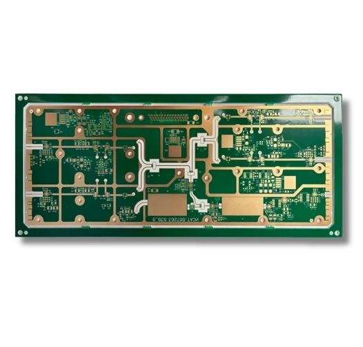
Rogers PCB Manufacturer for Medical Applications

MedPCB delivers ISO 13485-certified Rogers and hybrid circuit boards tailored for high-frequency medical imaging, RF ablation tools, and diagnostic systems. We focus on maintaining precise impedance control and low signal loss from initial prototyping through full volume production.

• ISO 13485 Certified Medical Manufacturing 
• Rogers & Hybrid Rogers-FR4 PCB Fabrication 
• Controlled Impedance & RF Stackup Support 
• Up to 40 Layers with HDI & Microvias

Medical Rogers PCB
Certifications
Why Choose Aluminum PCBs for Medical Devices?
introduction

Why Choose Rogers PCBs for Medical Electronic Devices?

Medical technology relies heavily on seamless wireless communication, precise signal transmission, and high-frequency imaging. At higher frequencies, conventional FR-4 may not provide the low-loss characteristics and dielectric stability required by demanding RF and microwave circuits. At high frequencies, FR4 suffers from significant signal attenuation and unstable dielectric constants, which can distort delicate medical readings.

Specialized Rogers high-frequency laminates solve this issue by offering ultra-low electrical losses and exceptional signal integrity. Because lives depend on accurate diagnostics, medical engineers choose Rogers substrates to guarantee dependable performance in critical healthcare environments. MedPCB specializes in manufacturing Rogers and hybrid Rogers-FR4 PCBs for demanding medical RF applications, helping you build more reliable medical devices that meet stringent industry standards.

Quality

Key Advantages of Rogers PCBs for Medical Devices

  • Ultra-Low Signal Loss for High-Frequency Medical Imaging
  • Stable Dielectric Constant Across Temperature and Frequency
  • Supports Precise Controlled Impedance
  • Low Moisture Absorption for Long-Term Medical Device Reliability
  • Excellent Thermal Stability for Sterilization and Harsh Clinical Environments
Ultra-Low Signal Loss for High-Frequency Medical Imaging
Advanced diagnostic tools require pristine signal clarity to produce accurate imagery. Rogers laminates feature exceptionally low dissipation factors, minimizing signal attenuation and ensuring that weak radio frequency signals from MRI coils or ultrasound transducers travel clearly without degradation.
Stable Dielectric Constant Across Temperature and Frequency
Clinical environments experience fluctuations in temperature, and medical devices operate across varying frequencies. Rogers materials maintain a remarkably stable dielectric constant, preventing unexpected phase shifts and frequency drifts so your diagnostic equipment delivers consistent, repeatable results every time.
Supports Precise Controlled Impedance
The stable dielectric properties of Rogers laminates make controlled impedance more predictable for high-frequency PCB projects. Combined with accurate stack-up construction, trace geometry control, and tight manufacturing tolerances, this helps reduce signal reflections, crosstalk, and insertion loss in your sensitive medical RF applications.
Low Moisture Absorption for Long-Term Medical Device Reliability
Medical electronics are frequently exposed to cleaning agents, sterilization processes, and humid clinic settings. Rogers materials possess very low moisture absorption rates, preventing water ingress from altering electrical properties and safeguarding the long-term reliability of your equipment.
Excellent Thermal Stability for Sterilization and Harsh Clinical Environments
Surgical and clinical tools must withstand rigorous cleaning and thermal cycles. Rogers PCBs offer robust thermal stability, resisting warping and physical degradation even when exposed to demanding sterilization procedures and continuous high-power operation.
Why Choose Us

Why Choose MedPCB?

  • ISO 13485 Certified Manufacturing

    ISO 13485 Certified Medical Manufacturing

    Our manufacturing facility operates under strict ISO 13485 guidelines specifically tailored for the medical industry. Every Rogers circuit board we produce is thoroughly documented and rigorously tested to satisfy the regulatory demands of global healthcare markets.

  • IPC-A-610 Class 3 Quality Acceptance

    Extensive Rogers Material Inventory

    We maintain a robust stock of popular Rogers laminates, including the RO4000 series, RO3000 series, and specialty PTFE materials. This extensive inventory allows us to bypass supply chain delays and start fabricating your medical boards right away.

  • Advanced Wave & Selective Soldering Technology

    Rogers Stackup & Hybrid Lamination Support

    Our engineering team reviews your proposed stackup and provides manufacturing recommendations for Rogers-FR4 hybrid constructions. We help optimize material combinations, lamination structures, and manufacturability while preserving your electrical design intent.

  • Medical-Grade Component Sourcing & BOM Support

    Advanced Manufacturing Capabilities

    Working with advanced high-frequency substrates demands specialized production techniques. Our facility is equipped with dedicated routing tools, laser-direct imaging systems, and plasma desmear lines to process delicate PTFE and ceramic-filled materials without compromising quality.

Specs

Technical Specifications

Order Quantity ≥ 1 PCS
Quality Grade IPC-6012 Class 2 & Class 3
Rogers Materials RO4350B, RO4003C, RO4835, RO3003, RO3006, RO3035, RT/duroid 5870, RT/duroid 5880, RT/duroid 6002, RT/duroid 6006, RT/duroid 6035HTC, and other Rogers high-frequency laminates available upon request.
Board Size 5 × 5 mm to 1100 × 500 mm (Standard up to 500 × 600 mm, Advanced up to 1100 × 500 mm)
Layer Count 1 to 40 layers (Standard: 1 to 20 layers; Advanced: 22 to 40 layers, including hybrid stackups)
Board Thickness 0.2 mm to 10.0 mm (Standard: 0.2 to 3.2 mm; Advanced: 3.4 to 10 mm)
Copper Thickness 17 µm to 350 µm (0.5 OZ to 10 OZ; Standard: min. 1/2 OZ, max. 4 OZ)
Min Trace Width/Spacing Internal: 3/3 mil (0.075 mm)
External: Down to 3/3 mil (Advanced) or 3.5/4 mil (Standard) depending on copper weight
Surface Finish Flash Gold, ENIG, Hard Gold, HASL Lead-Free, OSP, ENEPIG, Soft Gold, Immersion Silver, Immersion Tin, and combo finishes (e.g., ENIG+OSP, Gold Finger options)
Impedance Tolerance ±5 ohms (<50 ohms), ±10% (≥50 ohms)
Quality Inspection AOI, TDR Impedance Test, Hi-Pot, X-Ray, Microsection
Compliance ISO 13485, ISO 9001, RoHS, REACH, IPC-6012
Medical Rogers PCB
Capabillities

Our Medical Rogers PCB Production Process

Step 1: Engineering Review & Stackup Planning
Our engineering team thoroughly examines your Gerber files and RF requirements to verify manufacturability before production kicks off.
  • DFM Analysis: We review your layout to eliminate potential fabrication bottlenecks and ensure clean signal paths.
  • Material Selection: We help you choose the ideal Rogers laminate based on your specific frequency, dielectric constant, and thermal needs.
  • Stackup Recommendation: We design balanced layer stackups to minimize warping and crosstalk in multi-layer builds.
  • Controlled Impedance Planning: We calculate exact trace widths and spacing to guarantee precise impedance matching.
Step 2: Rogers Material Preparation
Handling high-frequency substrates requires a clean, controlled environment to protect sensitive material properties.
  • Material Conditioning: Raw panels are carefully conditioned to stabilize internal stresses prior to processing.
  • Moisture Control: We store and handle moisture-sensitive substrates in climate-controlled environments.
  • Imaging: High-resolution photolithography transfers your intricate RF circuit designs accurately onto the copper surfaces.
  • AOI: Automated Optical Inspection scans the inner layers for any microscopic defects or etching anomalies.
Step 3: Hybrid Lamination
Merging high-frequency Rogers materials with standard FR4 requires careful thermal management.
  • Bonding Film Selection: We choose compatible bonding films that offer low loss while ensuring secure structural adhesion.
  • Rogers–FR4 Lamination: Panels are aligned and pressed using specialized multi-zone heating cycles to prevent slipping.
  • Controlled Press Cycle: Temperature and pressure ramps are tightly monitored to avoid trapping air or creating voids.
  • Lamination Inspection: We perform strict physical and optical checks to confirm flawless bonding across the entire panel.
Step 4: Precision Drilling & Metallization
Creating clean vias through specialized laminates is critical for reliable electrical connectivity.
  • PTFE Drilling: We utilize specialized drill parameters and sharp bits to prevent burrs and smearing on soft substrates.
  • Plasma Desmear: Advanced plasma cleaning removes any resin residue from drilled holes, ensuring optimal plating adhesion.
  • Copper Plating: We deposit a uniform copper layer through the barrel of every via to guarantee strong interlayer connections.
  • Via Filling: Non-conductive or conductive epoxy fills vias where required for flat surface mounting and thermal paths.
Step 5: Final Surface Finish & RF Verification
Every board undergoes rigorous finishing and testing procedures to ensure it meets medical-grade performance standards.
  • Surface Finish: Depending on your project requirements, we offer surface finishes including ENIG, ENEPIG, and Immersion Silver, plus custom plating options as requested. These coatings shield exposed copper from oxidation and create stable pads for consistent soldering.
  • Controlled Impedance Test: Time-domain reflectometry testing verifies that trace impedances fall strictly within your requested tolerance range.
  • Electrical Test: Rigorous open- and short-circuit testing ensures every electrical pathway functions correctly.
  • Final Inspection: Our quality assurance team conducts a thorough visual and dimensional examination before secure packaging.
Quality Control

Common Challenges in Medical Rogers PCB Fabrication

  • Through-Hole Solder Fill Reliability

    PTFE Material Handling and Dimensional Stability

    Soft PTFE-based laminates can easily stretch or warp during standard handling and thermal processing, ruining fine-pitch alignments.

    Our Solution: We implement strict tension controls, specialized handling procedures, and low-stress baking cycles to keep panels dimensionally stable throughout manufacturing.

  • Preventing Thermal Damage to Sensitive Components

    Copper-to-Dielectric Adhesion on Low-Loss Substrates

    Because low-loss high-frequency materials lack natural bonding roughness, copper foils can delaminate during thermal stress.

    Our Solution: We utilize specialized chemical surface treatments and proprietary bonding protocols to lock the copper foil securely to the smooth substrate.

  • Thermal Expansion and Warpage Control

    Impedance Deviation Control in Tight-Tolerance Designs

    Minor variations in dielectric thickness or etching width can cause significant impedance shifts in high-frequency circuits.

    Our Solution: We use impedance test coupons, TDR testing, and tightly controlled etching processes to verify impedance accuracy and maintain the required tolerance for high-frequency circuits.

  • BGA Rework and Repair Challenges

    Hybrid Stackup Delamination Prevention

    Combining different material families like Rogers and FR4 often leads to delamination due to mismatched thermal expansion rates.

    Our Solution: We engineer balanced hybrid stackups using specialized low-flow prepregs and customized lamination press profiles that absorb thermal stress effectively.

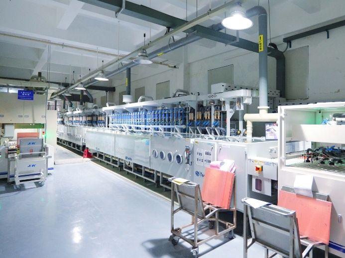
Our PCB Factory
Types

Rogers Materials Commonly Used in Medical Devices

RO4000 Series (RO4350B, RO4003C)

Hydrocarbon-based ceramic laminates with low dielectric loss, stable electrical properties, and FR-4-like processing characteristics. These materials are suitable for multilayer medical RF circuits, wireless modules, imaging electronics, and other applications requiring controlled high-frequency performance.

RO3000 Series (RO3003, RO3010)

Ceramic-filled PTFE laminates designed for demanding RF and microwave applications. Their stable dielectric properties and low electrical loss make them suitable for antenna circuits, phased-array systems, and other medical electronics requiring precise high-frequency signal transmission.

RT/duroid Series (5880, 5870)

PTFE-based high-frequency laminates covering a range of dielectric constants, loss levels, and thermal performance requirements. These materials can support low-loss RF circuits, antenna structures, compact microwave designs, and higher-power applications requiring enhanced thermal management.

TMM Series (TMM3, TMM4, TMM6)

Thermoset microwave materials that combine the mechanical stability of ceramics with the processing ease of resins. They provide excellent thermal stability for medical equipment operating in extreme clinical settings.

Need a reliable Rogers PCB manufacturing partner? Send us your Gerber files for a free DFM review and fast quotation.

Case Study

Medical Aluminum PCB Cases

  • MRI Phased Array RF Coil PCB on RO4350B
    MRI Phased Array RF Coil PCB on RO4350B MRI Phased Array RF Coil PCB on RO4350B

    MRI Phased Array RF Coil PCB on RO4350B

    A medical imaging client needed a high-frequency board to upgrade their MRI receiver coils. We fabricated a multi-layer circuit using RO4350B material with strict impedance control. The finished PCB delivered stable impedance control and low insertion loss, helping improve overall image quality and reduce signal artifacts.

  • RF Ablation Generator High-Power Amplifier Board
    RF Ablation Generator High-Power Amplifier Board RF Ablation Generator High-Power Amplifier Board

    RF Ablation Generator High-Power Amplifier Board

    An equipment manufacturer struggled with thermal management and signal integrity inside their surgical ablation generators. We engineered a hybrid Rogers-FR4 circuit board that provided stable RF signal transmission and reliable thermal performance during continuous operation.

  • Ultrasound Beamformer Interface Using RO4003C
    Ultrasound Beamformer Interface Using RO4003C Ultrasound Beamformer Interface Using RO4003C

    Ultrasound Beamformer Interface Using RO4003C

    A client developing next-generation ultrasound equipment required tight phase accuracy across multiple channels. We delivered a precision RO4003C board that eliminated signal drift, allowing the diagnostic scanner to render sharper and more accurate deep-tissue images.

  • Implantable Cardiac Device Telemetry on RT/duroid 5880
    Implantable Cardiac Device Telemetry on RT/duroid 5880 Implantable Cardiac Device Telemetry on RT/duroid 5880

    Implantable Cardiac Device Telemetry on RT/duroid 5880

    A medical device maker needed an exceptionally reliable substrate for a wireless telemetry module. We utilized low-loss RT/duroid 5880 laminates to ensure secure, uninterrupted data transmission while meeting strict biocompatibility and reliability guidelines.

Faqs

Frequently Asked Questions

Our Medical Rogers PCB FAQ addresses essential questions regarding your manufacturing requirements. We cover our capabilities for high-frequency Rogers laminates, hybrid lamination stackups, precise impedance control, strict IPC-6012 quality standards, and seamless scalability from quick-turn prototypes to mass production. For every medical Rogers PCB project, we guarantee high-precision fabrication tailored for critical RF and signal-sensitive healthcare applications.

1. Why Are Rogers Materials Preferred Over FR4 for Medical RF Applications?
Parameter / Metric Standard FR4 Rogers High-Frequency Materials
High-Frequency Performance Moderate; suitable mainly for digital and lower-frequency analog circuits. Excellent; engineered specifically for high-frequency RF and microwave applications.
Dielectric Constant (Dk) Stability Varies significantly across temperature and wide frequency ranges, risking signal distortion. Exceptionally stable across varying temperatures and frequencies, ensuring reliable phase control.
Electrical Signal Loss (Df / "Loss Tangent") Higher dissipation factor (≈0.015-0.020), leading to severe signal attenuation at higher frequencies. Ultra-low loss tangent (≈0.002-0.004), preserving weak medical telemetry and imaging signals.
Impedance Control Precision Moderate tolerance control; vulnerable to thickness variations in high-frequency layouts. High precision; maintains tight impedance control (within ±5%) for sensitive RF circuits.
Moisture Absorption Higher (typically >0.25%), which can alter electrical properties over time in humid clinical settings. Extremely low moisture absorption, protecting long-term device reliability and performance.
Medical Application Suitability Standard power supplies and basic control interfaces. MRI receiver coils, ultrasound beamformers, surgical RF ablation, and wireless implantable telemetry.
2. What Rogers Series Is Best for High-Frequency Medical Imaging?
The RO4000 series is ideal for most medical RF and imaging applications due to its excellent electrical performance and cost-effective manufacturing compatibility. For extremely sensitive microwave frequencies, our RT/duroid series is often the preferred choice.
3. Does MedPCB Support Rogers-to-FR4 Hybrid Laminations?
Yes. We fabricate hybrid circuit boards that combine high-frequency Rogers materials on outer layers with cost-effective FR4 on inner layers, helping you optimize both performance and project budget.
4. How Do You Ensure Consistent DK/DF Across Medical PCB Batches?
We source materials exclusively from trusted suppliers, inspect incoming lots rigorously, and maintain strict process controls in our lamination and etching departments to ensure uniform dielectric constants across every production run.
5. Can You Manufacture Multilayer Rogers PCBs for Medical Devices?
Yes. While many high-frequency boards are single or double-sided, we frequently fabricate complex multilayer Rogers and hybrid boards containing up to 40 layers for advanced medical electronics.
6. What Surface Finishes Work Best with Rogers High-Frequency Laminates?
Electroless Nickel Immersion Gold (ENIG) and Electroless Nickel Electroless Palladium Immersion Gold (ENEPIG) are our top recommendations. They provide flat, highly solderable surfaces that protect high-frequency traces without introducing signal loss.
7. How Do You Handle PTFE-Based Rogers Material Drilling?
We use specialized diamond-coated drill bits, optimized spindle speeds, and custom feed rates designed specifically for soft substrates, preventing burrs and protecting the integrity of the board edges.
8. What Minimum Trace Width and Spacing Can You Achieve on Rogers?
Depending on copper thickness and material selection, we routinely achieve fine-line trace widths and spacing down to 0.075 mm, supporting dense high-frequency medical layouts.
9. Do You Offer Controlled Impedance Testing and TDR Reports?
Yes. Every controlled impedance batch undergoes thorough Time Domain Reflectometry testing, and we provide detailed TDR reports with your shipment to verify compliance with your design specifications.
10. Can MedPCB Source Specific Rogers Laminates for Low-Volume Medical Prototypes?
Yes. We maintain an agile manufacturing setup equipped to handle low-volume prototype runs, allowing you to test and validate your high-frequency medical designs quickly before moving to mass production.
11. What IPC Class Is Your Medical Rogers PCB Manufacturing Certified For?
We manufacture medical boards to strict IPC-6012 Class 2 standards, with full capabilities available for Class 3 compliance depending on your product requirements.
12. How Do You Maintain Traceability in Medical-Grade Rogers PCB Production?
We maintain end-to-end documentation tracking material lot numbers, processing parameters, and inspection results throughout every stage of fabrication to ensure complete transparency and compliance.
13. Can You Provide Laser-Direct Imaging (LDI) for Fine-Pitch Rogers Designs?
Yes. Our facility features advanced Laser-Direct Imaging systems that bypass traditional photomasks, enabling exceptional alignment accuracy for ultra-fine-pitch high-frequency circuits.

Product Related