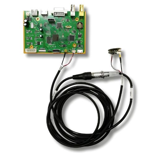
Medical Endoscope PCB

Medical endoscope PCBs support image capture, LED lighting, signal processing, power management, and control functions. These boards require compact construction, high-density routing, reliable image signal transmission, and stable performance. MedPCB manufactures and assembles medical-grade PCBs for endoscopes and other minimally invasive imaging devices.

✔ Rigid, Flex, HDI & Rigid-Flex PCB Options For Compact Endoscope Designs
✔ Fine-Pitch SMT Assembly for Compact Endoscope PCBAs
✔ Component Sourcing, Inspection & Functional Testing
✔ ISO 13485 Manufacturing & IPC Class 2/3 Support

Medical Endoscope PCB
Certifications
What is Medical Endoscope PCB
introduction

What is Medical Endoscope PCB?

A medical endoscope PCB is a specialized circuit board used inside medical endoscopes and imaging systems. It supports key electronic functions, including image capture, LED illumination, image signal processing, power management, and device control.

Medical endoscope PCBs must handle high-speed image signals while maintaining stable electrical performance. The PCB also needs compact construction, low noise, reliable signal transmission, and precise component placement. Small endoscope designs may require HDI, fine-pitch components, flexible circuits, or rigid-flex PCB construction.

MedPCB manufactures and assembles medical-grade PCBs for medical endoscopes. We support rigid, flex, rigid-flex, HDI, and multilayer PCB designs. Our manufacturing supports prototypes, low-volume production, and volume manufacturing.

Quality

Features of Medical Endoscope PCB

  • High-Density Integration for Compact Endoscopes
  • Flex & Rigid-Flex for Flexible Structures
  • High-Speed Signal Transmission
  • LED Illumination
High-Density Integration for Compact Endoscopes
Medical endoscopes require compact electronics for imaging, illumination, control, and signal transmission. HDI PCBs and fine-pitch PCBA support higher component density within limited board space, making them suitable for compact endoscope tips, handles, and other space-constrained assemblies.
Flex & Rigid-Flex for Flexible Structures
High-Speed Signal Transmission
LED Illumination
Why Choose Us

MedPCB for Medical Endoscope PCB Manufacturing

  • ISO 13485 Certified Halogen-Free PCB Production

    ISO 13485 PCB & PCBA Manufacturing

    MedPCB manufactures all medical endoscope PCBs and PCBAs under an ISO 13485 certified quality management system. Our strict process controls ensure complete material traceability, regulatory compliance, and consistent quality from initial build to volume production.

  • HDI, Flex & Rigid-Flex PCB Manufacturing

    HDI, Flex & Rigid-Flex PCB Manufacturing

    We manufacture HDI, multilayer, flex, and rigid-flex PCBs for compact medical electronics. Our capabilities include fine-line routing, microvias, controlled impedance, and complex rigid-flex constructions according to your approved design requirements.

  • Ultra-Fine Pitch Component Assembly

    Ultra-Fine Pitch Component Assembly

    MedPCB supports 01005 components, fine-pitch ICs, QFN, BGA, and other high-density packages for compact endoscope PCBAs. SPI, AOI, and X-ray inspection are applied according to assembly requirements.

  • Full Turnkey Capability

    Full Turnkey Capability

    MedPCB provides complete PCB fabrication and assembly services, including component sourcing, SMT and THT assembly, inspection, and functional testing. This supports endoscope PCBA production from prototypes to volume manufacturing.

  • Free DFM / DFA Check

    Free DFM / DFA Check

    Our engineering team reviews the PCB layout, stackup, trace spacing, component placement, drilling, and assembly requirements before production. This helps identify manufacturing and assembly issues early and supports reliable endoscope PCB production.

Specs

Technical Specifications

Technical Parameter

Manufacturing Capability

Order Quantity

≥ 1 PCS, No MOQ

Board Size

Standard: up to 500 × 600 mm; Advanced: up to 1100 × 500 mm

Layer Count

Rigid PCB: 1–40 layers 
Flex PCB: 1 to 8 Layers

Rigid Flex PCB: Standard: 2–12 layers (up to 10 flex layers), Advanced: 13–20 layers (up to 18 flex layers)

Assembly Technologies

Surface Mount (SMT), Through-Hole (THT/DIP), and Mixed-Technology

Component Sourcing

Full Turnkey, Partial Turnkey, or Consigned (access to 300,000+ genuine parts)

Component Range

From 01005 packages to 0.2 mm fine-pitch BGAs

Placement Accuracy

±0.035 mm via automated component placement

Board Thickness

0.2–10.0 mm (Standard: 0.2–3.2 mm; Advanced: 3.4–10.0 mm)

Min. Trace Width / Spacing

Internal: 3/3 mil (0.075 mm); External: 3/3 mil advanced, 3.5/4 mil standard

Surface Finish

ENIG, ENEPIG, Lead-Free HASL, OSP, Immersion Silver, Immersion Tin, Soft/Hard Gold, 

Impedance Tolerance

±5 Ω for <50 Ω; ±10% for ≥50 Ω

Materials

High-Tg FR-4, Polyimide (Flex), Rogers, Megtron 6, and Other Qualified PCB Materials

Technical Specification Medical Endoscope PCB
Capabilities

Medical Endoscope PCB Manufacturing and Assembly on MedPCB

Step 1: Engineering Review & DFM/DFA

We review your medical endoscope PCB design before production. Our engineers check the layout, pad design, trace spacing, impedance requirements, component placement, flex or rigid-flex structure, and assembly details. This helps identify potential manufacturing issues early.

Step 2: PCB Fabrication & Component Sourcing
Step 3: IQC Incoming Quality Inspection
Before assembly, our quality team inspects incoming PCBs and components. We check part numbers, quantities, packaging, specifications, material condition, and available traceability records. Materials are released to production only after inspection.
Step 4: SMT & THT Assembly
We assemble medical endoscope PCBAs using automated and manual SMT and THT processes. The process includes solder paste printing, fine-pitch component placement, reflow soldering, and through-hole assembly. We support compact components from 01005 packages to fine-pitch BGAs, along with assembly of packaged image-sensor components according to project requirements
Step 5: Inspection, Testing & Traceability
Finished endoscope PCBAs undergo inspection and testing based on project requirements. AOI checks solder joints and component placement, while 3D X-ray inspects hidden connections such as BGAs and other bottom-terminated components. Electrical and functional testing verify board performance. Production and inspection records are maintained to support full project traceability.
challenges

Challenges in Medical Endoscope PCB Manufacturing and Assembly

  • Rigid-Flex Transitions

    Rigid-Flex Transitions 

    Challenge: Medical endoscopes use flex and rigid-flex PCBs in the distal tip, insertion tube, handle, and processor sections. These areas undergo repeated bending and movement. The rigid-to-flex transition can experience high mechanical stress, especially during scope articulation. 

    Our Solution: MedPCB manufactures flex and rigid-flex PCBs with controlled transition areas. Stiffeners can support component and connector zones, while gradual trace fan-out helps reduce stress. Controlled fabrication also supports reliable rigid-flex connections and consistent mechanical performance.

  • Miniaturization and Fine-Pitch Assembly

    Miniaturization and Fine-Pitch Assembly

    Challenge: The endoscope tip has very limited space for the CMOS image sensor, LEDs, timing and communication circuits, and other components. Designs may require HDI, multilayer construction and 01005 components. 

    Our Solution: MedPCB manufactures HDI, multilayer, flex, rigid, and rigid-flex PCBs for compact endoscope designs. We support ultra-fine pitch SMT from 01005 packages to 0.2 mm BGAs. AOI, 3D X-ray, and electrical testing help verify high-density assemblies.

  • High-Speed & Controlled-Impedance PCB Manufacturing

    High-Speed & Controlled-Impedance PCB Manufacturing

    Challenge: Endoscope electronics may use high-speed image and communication interfaces across compact rigid, flex, or rigid-flex circuits. These designs can require tight control of trace geometry, stackup, and impedance during PCB fabrication.

    Our Solution: MedPCB manufactures controlled-impedance PCBs according to the approved stackup and impedance requirements. We control material selection, copper thickness, trace geometry, dielectric thickness, and fabrication tolerances, with impedance testing available when specified.

  • Component Density and Signal-Sensitive Areas

    Component Density and Signal-Sensitive Areas

    Challenge: Compact endoscope PCBAs can have dense component spacing and signal-sensitive areas where flux residue, contamination, or improper cleaning may affect assembly quality. Some applications may also require additional protection against moisture or environmental exposure.

    Our Solution: MedPCB controls cleaning and handling according to the approved assembly requirements. Cleanliness inspection, conformal coating, and encapsulation can be provided when specified by the product design and environmental requirements.

Medical Endoscope PCBPCBA Testing & Validation in MedPCB
Specs

Medical Endoscope PCB/PCBA Testing & Validation in MedPCB

PCB Inspection & Electrical Testing
We inspect your endoscope PCBs throughout fabrication using AOI, dimensional inspection, and electrical testing. Controlled-impedance testing can also be performed when required by your design.

PCBA Process Inspection
We inspect component placement, solder joints, and assembly quality during the PCBA process. 3D SPI checks solder paste volume and placement before component assembly. AOI verifies component position, polarity, solder joints, and other visible defects. X-ray inspection can check hidden solder joints on BGAs, QFNs, and other high-density components.

Functional Testing & Traceability
We perform functional testing based on your approved test requirements. Tests can verify power circuits, communication interfaces, image signal paths, LED illumination, and other endoscope functions. Production records and component information are maintained for lot traceability and quality control.

Need reliable Medical Endoscope PCB & PCBA? Send your Gerber files, BOM, and assembly files to sales@medicalpcb.com for a free DFM/DFA review.


Case Study

Medical Endoscope PCB Case Studies

  • Distal Tip (Sensor)
    Distal Tip (Sensor) PCB Distal Tip (Sensor)

    Distal Tip (Sensor) PCB

    For micro-tip assembly, the customer required an ultra-compact distal tip endoscope PCB under 2 mm in width. MedPCB fabricated a high-density SMD layout like image sensors, micro-LEDs, and sensor drivers directly into the scope head. The completed assemblies passed strict dimensional and 3D optical inspections.

  • Insertion Shaft
    Insertion Shaft PCB Insertion Shaft

    Insertion Shaft PCB

    For dynamic scope bending, the customer needed an ultra-flexible, multi-layer flex endoscope PCB to transmit high-speed raw video signals. MedPCB produced a high-durability flex circuit featuring continuous EMI shielding to protect video clarity across the shaft length. The finished flex boards passed extreme bend-life and signal integrity testing.

  • Control Handle
    Control Handle PCB Control Handle

    Control Handle PCB

    For ergonomic grip integration, the customer requested a durable control handle endoscope PCB to manage water flush, image capture, and zoom functions. MedPCB manufactured a multi-layer rigid-flex HDI PCB designed for tight mechanical tolerances and high user-actuation longevity. The completed boards passed mechanical strain and tactile switch functional testing.

  • Video Processing Unit (VPU)
    Video Processing Unit (VPU) PCB Video Processing Unit (VPU)

    Video Processing Unit (VPU) PCB

    For real-time 4K/HD imaging, the customer required a high-performance endoscope PCB to convert raw camera signals into broadcast-quality video streams. MedPCB built a high-layer rigid HDI FR-4 board featuring advanced FPGAs/DSPs, high-speed trace routing, and medical-grade electrical isolation. The finished assemblies passed full functional signal integrity and safety compliance testing.

  • Light Engine & Power Driver
    Light Engine & Power Driver PCB Light Engine & Power Driver

    Light Engine & Power Driver PCB

    For high-intensity laser diode and LED control, the customer needed a thermally resilient endoscope PCB. MedPCB fabricated a heavy-copper metal core PCB (MCPCB) engineered for rapid heat dissipation and voltage surge protection. The completed boards passed thermal imaging, high-voltage isolation, and continuous burn-in testing.

Faqs

Frequently Asked Questions

Our Medical Endoscope PCB FAQ covers key questions about endoscope PCB manufacturing and assembly. We explain our capabilities for compact, high-precision circuits, rigid, flex, and rigid-flex PCBs, material selection, miniature component assembly, and strict ISO 13485 quality standards. We also cover RoHS and REACH compliance, testing, and reliability requirements for medical imaging and diagnostic devices.

1. What Is The Smallest PCB Diameter Possible For A Medical Endoscope?
MedPCB manufactures endoscope tip PCBs as small as 1.0 mm in diameter, depending on sensor size, LED count, and routing needs. We utilize ultra-fine HDI microvias and sequential build-up techniques to pack complex MIPI signals and power decoupling into micro-tip geometries.
2. Why Do Endoscope PCBs Need To Survive 134°C Autoclave Cycles?
Reusable endoscopes undergo saturated steam sterilization at 134°C to eliminate all pathogens between procedures. Our endoscope PCBs use high-Tg laminates, specialized solder masks, and ENIG surface finishes to withstand repeated thermal shock without delamination or signal loss.
3. Can Rigid-Flex PCBs Replace Discrete Wires In An Endoscope Insertion Tube?
Yes. Rigid-flex PCBs replace bulky wire bundles, reducing insertion tube diameter, lowering assembly labor, and minimizing joint failures in high-flex articulation zones.
4. What Materials Are Used For Endoscope PCBs?
We use flexible polyimide substrates for insertion shafts to ensure maximum flex life and thermal stability. For control sections and VPUs, polyimide flex is combined with high-Tg FR-4, Megtron 6, or metal-core laminates to form durable rigid-flex and HDI structures.
5. What Protection Options Are Available for Endoscope PCBAs?
MedPC supports PCBA cleaning, conformal coating, and encapsulation according to project requirements. The required protection process depends on the device construction, operating environment, and approved material specifications.
6. What Quality Standards Apply For Medical Endoscope PCBs?
Medical endoscope PCBs must comply with ISO 13485 quality management, IPC-Class 3 high-reliability manufacturing standards, IEC 60601-1 electrical safety standards, and ISO 10993 biocompatibility requirements.
7. What Is The Life Cycle Of An Endoscopic PCB?
The life cycle ranges from 1 to 10+ years depending on device type. Single-use disposable endoscopes are engineered for a single procedure, while reusable surgical scopes are built to survive 100 to 500+ autoclave sterilization cycles without performance degradation.

Product Related