Rogers RT/duroid 6035HTC Medical PCB Manufacturer

MedPCB manufactures Rogers 6035HTC PCBs for medical electronics that require high RF power handling, low signal loss, and effective thermal management.

• 1.44 W/m/K Thermal Conductivity, suitable for medical high‑power RF applications
• Low Df of 0.0013 at 10 GHz for Low-Loss Signals 
• Dk 3.50 ± 0.05 for Stable RF Performance 
• Ceramic‑Filled PTFE PCB Fabrication
• ISO 13485 & IPC Class 2/3 Manufacturing

Rogers RTduroid 6035HTC Medical PCB Manufacturer
Certifications
What Is Rogers 6035HTC?
introduction

What Is Rogers 6035HTC?

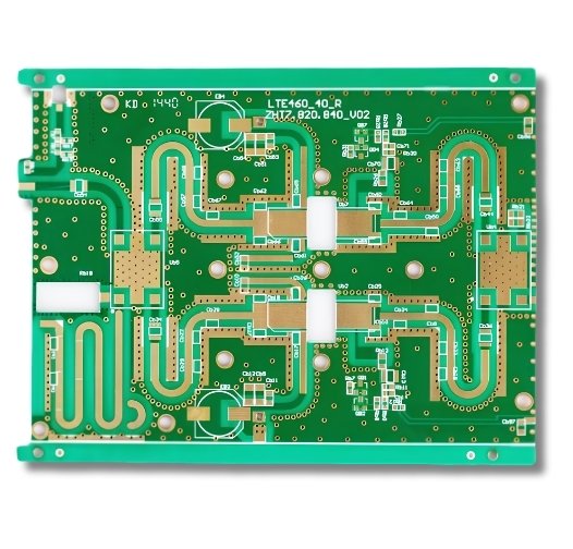
Rogers RT/duroid 6035HTC is a ceramic-filled PTFE composite laminate for high-power RF and microwave circuits. The HTC designation refers to its high thermal conductivity filler system, which raises thermal conductivity well above that of the standard RT/duroid 6000 grades while keeping the low dielectric loss expected of a PTFE microwave material.

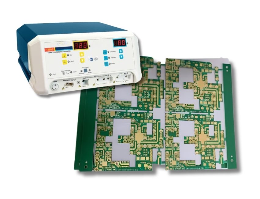
Medical RF equipment is usually limited by heat rather than loss. Ablation generators and electrosurgical output stages dissipate real power, and 6035HTC carries that heat out of the dielectric while keeping microwave loss low. The tight dielectric tolerance matters too, since a validated device is built to a frozen design and needs electrical length to repeat across lots.

MedPCB fabricates single-sided, double-sided, multilayer PTFE, and PTFE/FR-4 hybrid boards on genuine Rogers 6035HTC for medical device programs, with lot-level material traceability and production records aligned to ISO 13485.

advantages

Key Advantages of Rogers 6035HTC for Medical PCB Manufacturing

  • High Thermal Conductivity for High-Power RF Applications
  • Stable Dielectric Constant for Repeatable RF Calibration
  • Low Dissipation Factor for Microwave Signal Integrity
  • Low Z-Axis Expansion for Plated Via Reliability
  • Thermally Stable Copper Foil for RF Signal Integrity
High Thermal Conductivity for High-Power RF Applications
With a thermal conductivity of 1.44 W/m/K, 6035HTC supports heat dissipation from high-power RF circuits. This makes it suitable for medical electronics where RF performance and thermal management need to be considered together, such as electrosurgical and ablation equipment.
Stable Dielectric Constant for Repeatable RF Calibration
Low Dissipation Factor for Microwave Signal Integrity
Low Z-Axis Expansion for Plated Via Reliability
Thermally Stable Copper Foil for RF Signal Integrity
Why Choose Us

Why Choose MedPCB for Rogers 6035HTC?

  • PTFE Drilling and Plating Control

    ISO 13485 Certified Rogers 6035HTC PCB Production

    We build 6035HTC boards under ISO 13485 and ISO 9001 certification. Every panel lot carries recorded process data for plasma treatment, drilling, lamination, and plating. Boards are inspected to IPC-6012 Class 2 or Class 3. Device history record support, deviation handling, and change control follow your supplier quality agreement.

  • Drill Registration & Hole Wall Control

    Free DFM Review for Your 6035HTC PCB Project

    Our engineering team reviews your Gerber files, stackup, drill data, and fabrication requirements before production. We check trace width and spacing, dielectric thickness, drill-to-copper clearance, annular rings, impedance requirements, and other manufacturability details for PTFE and high-frequency PCB fabrication. We then provide DFM feedback based on the specified board construction.

  • Multilayer Lamination and Registration

    Rogers 6035HTC Material Sourcing

    We source genuine Rogers RT/duroid 6035HTC in the required laminate thickness, copper weight, and foil type. Material certificates and lot information are maintained for production traceability and quality control.

  • Copper Surface and RF Loss Control

    PTFE Multilayer & Hybrid Stackup Fabrication

    We support multilayer PTFE PCB fabrication and hybrid constructions that combine high-frequency materials with conventional PCB materials where required by the design. Our engineering team evaluates the stackup, material compatibility, dielectric thickness, copper distribution, and thermal expansion before production to support reliable multilayer fabrication.

  • Precision Drilling and Plating for PTFE PCBs

    Precision Drilling and Plating for PTFE PCBs

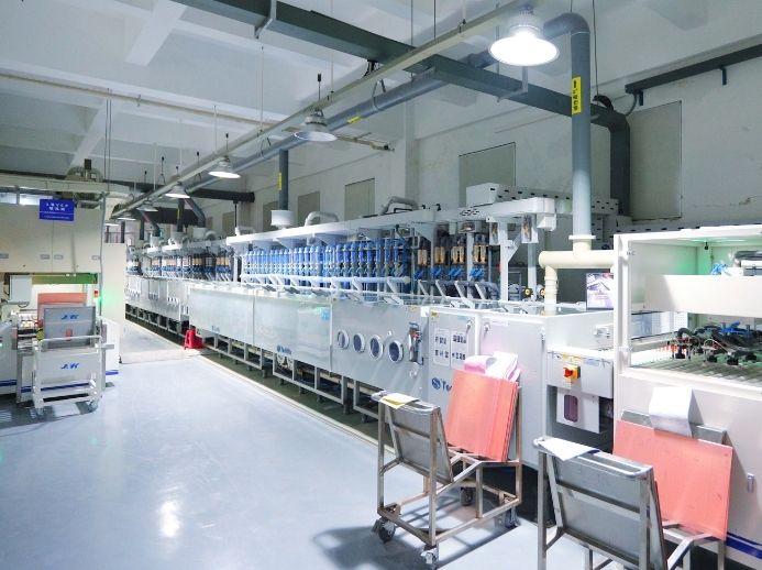
    Hole walls are where PTFE boards fail. We drill with parameters developed for filled PTFE, activate every hole wall by plasma before electroless copper, and confirm hole wall quality by microsection on production panels, not only on first articles.

  • Quality Assurance & Reliability Testing

    Quality Assurance & Reliability Testing

    We use AOI, electrical testing, dimensional inspection, and other inspection methods according to the PCB design and customer requirements. X-ray inspection, impedance testing, microsection analysis, and reliability testing are available for projects that require additional process verification. Inspection records and material traceability documents can be provided according to the agreed quality plan.

Specs

Technical Specifications

Capability Standard Advanced
PCB Type Rigid PCB, rigid-flex; heavy copper, blind & buried via, backdrill
Layer Count 1–20 layers 22–40 layers
Finished Board Thickness 0.2–3.2 mm 3.4–10 mm
Max. Board Size 500 × 600 mm (19″ × 23″) 1100 × 500 mm (43″ × 19″)
Copper Thickness 1/2 oz min, 4 oz max 1/3 oz min, 10 oz max
Min. Trace / Space, outer layer 3.9 / 4.5 mil (1/2 oz); 4.8 / 5 mil (1 oz) 3.5 / 3.5 mil (1/2 oz); 3 / 3 mil (1/3 oz)
Min. Trace / Space, inner layer 3 / 3 mil (1/2 oz); 3 / 4 mil (1 oz) Same
Max. Aspect Ratio, PTH 10:1 (hole diameter > 8 mil) 20:1
Min. Laser Drill 4 mil 4 mil
Hole Position Tolerance ±2 mil ±2 mil
Outline Tolerance 0.15 mm (6 mil) 0.10 mm (4 mil)
Warp and Twist 0.75% 0.50%
Impedance Control ±5 Ω (< 50 Ω), ±10% (≥ 50 Ω)
Surface Finish ENIG, ENEPIG, soft gold, hard gold, flash gold, immersion silver, immersion tin, OSP, HASL lead-free; ENIG+OSP and gold finger combinations
Standards IPC-6012 Class 2 / Class 3, IPC-A-600, ISO 13485, ISO 9001
Medical Rogers 6035HTC PCB
Process

Our Rogers 6035HTC Manufacturing Process

Step 1: Engineering Review & Rogers 6035HTC Material Verification
Our engineering team reviews the Gerber files, stackup, material requirements, copper thickness, and impedance specifications before production. We verify the Rogers 6035HTC material against the required thickness, copper weight, and supplier documentation before fabrication.
Step 2: Inner Layer Fabrication & Multilayer Lamination
Step 3: Controlled Drilling & Hole Preparation
Step 4: Copper Plating & Outer Layer Fabrication
Step 5: Surface Finish & Final Inspection
challenges

Common Challenges in Rogers 6035HTC Fabrication

  • PTFE Drilling and Plating Control

    PTFE Drilling and Plating Control

    PTFE-based laminates require specialized drilling and hole preparation to achieve reliable copper plating. Poor hole-wall preparation can affect plating adhesion and long-term interconnection reliability.

    Our Solution: MedPCB uses PTFE-specific drilling and hole preparation processes before copper plating. We control hole quality and plating conditions throughout fabrication, with microsection analysis and electrical testing performed according to the project requirements.

  • Drill Registration & Hole Wall Control

    Drill Registration & Hole Wall Control

    PTFE is a soft matrix that smears under heat, so a dulling bit or an excessive feed rate leaves resin on the hole wall and blocks plating adhesion. The material is also less rigid than epoxy laminate, so drill deflection on thicker panels appears as annular ring breakout on the layers furthest from the entry side.

  • Multilayer Lamination and Registration

    Multilayer Lamination and Registration

    PTFE requires a higher lamination temperature than epoxy systems and moves differently through the cycle, so layer-to-layer registration drifts in ways that FR-4 process settings do not predict. In hybrid stackups the expansion mismatch between PTFE and epoxy adds warp and concentrates stress at the interface.

  • Copper Surface and RF Loss Control

    Copper Surface and RF Loss Control

    At microwave frequencies most conductor loss occurs at the copper-dielectric interface, so foil roughness, etched sidewall profile, and surface finish all contribute to measured insertion loss. A board that meets its dimensional drawing can still miss its loss budget, and this is usually found during system-level testing.

Rogers RT/duroid 6035HTC Material Specifications
Specifications

Rogers RT/duroid 6035HTC Material Specifications

The table below lists published typical values for Rogers RT/duroid 6035HTC ceramic-filled PTFE laminate. Testing follows IPC-TM-650 standard test procedures unless otherwise noted.

Property Rogers RT/duroid 6035HTC Method / Condition
Dielectric Constant (Process Dk) 3.50 ± 0.05 10 GHz, 23°C, IPC-TM-650 2.5.5.5
Design Dielectric Constant (Design Dk) 3.60 Differential Phase Length Method, 8-40 GHz
Dissipation Factor (Df / tan δ) 0.0013 10 GHz, 23°C, IPC-TM-650 2.5.5.5
Thermal Conductivity 1.44 W/m/K 80°C, ASTM C177
Thermal Coefficient of Dk (TC Dk) -65 ppm/°C 10 GHz, -50°C to 150°C, IPC-TM-650 2.5.5.5
Coefficient of Thermal Expansion (CTE, X/Y-Axis) 19 / 19 ppm/°C 0°C to 100°C, IPC-TM-650 2.4.41
Coefficient of Thermal Expansion (CTE, Z-Axis) 39 ppm/°C 0°C to 100°C, IPC-TM-650 2.4.41
Decomposition Temperature (Td) >500°C TGA, 5% weight loss
Water Absorption 0.06% D-24/23, IPC-TM-650 2.6.2.1
Volume Resistivity 2.0 × 10⁷ MΩ·cm IPC-TM-650 2.5.17.1
Surface Resistivity 3.0 × 10⁷ MΩ IPC-TM-650 2.5.17.1
Flammability Rating V-0 UL 94
Copper Foil Options Reverse-Treated Electrodeposited (Electrodeposited / Treated) 1/2 oz (18 µm), 1 oz (35 µm), 2 oz (70 µm)
Standard Thicknesses 0.010″, 0.020″, 0.030″, 0.040″, 0.060″ Dielectric Thickness Tolerances apply

Need a Rogers RT/duroid 6035HTC high-frequency PTFE PCB for a high-power medical RF program? Send Your Gerber Files for a Free DFM Review.

industries

Applications of Rogers 6035HTC Medical PCBs

More Industries

Case Study

Medical Rogers 6035HTC PCB Case Studies

  • 12-Layer Microwave Ablation Catheter Antenna PCB
    12-Layer Microwave Ablation Catheter Antenna PCB 12-Layer Microwave Ablation Catheter Antenna PCB

    12-Layer Microwave Ablation Catheter Antenna PCB

    The project required stable antenna performance in a high layer count build with limited board area. MedPCB fabricated the 12-layer PCB according to the customer's stackup, impedance, dimensional, and inspection requirements, including the specified material assignment and copper weights for each layer pair. Controlled-impedance testing, electrical test, and production inspection were performed where specified by the project.

  • Electrosurgical Generator Board with High-Voltage Isolation
    Electrosurgical Generator Board with High-Voltage Isolation Electrosurgical Generator Board with High-Voltage Isolation

    Electrosurgical Generator Board with High-Voltage Isolation

    The governing requirements here were dissipation at the output stage and clearance at the high-voltage nodes. We built a hybrid stackup with 6035HTC on the RF and power layers over FR-4 cores, with a thermal via array under the output devices sized and plated for the through-thickness expansion of the laminate. Spacing and mask coverage were verified against the customer's stated working voltage, and the lot was released after thermal stress coupons, AOI, and microsection.

  • MRI Coil Array with Controlled Impedance Verification
    MRI Coil Array with Controlled Impedance Verification MRI Coil Array with Controlled Impedance Verification

    MRI Coil Array with Controlled Impedance Verification

    The project required consistent electrical performance across multiple RF channels. MedPCB manufactured the Rogers 6035HTC PCB according to the customer's stackup, impedance, dimensional, and inspection requirements. Controlled-impedance testing and production inspection were performed where specified by the project.

  • Implant Telemetry Module with Full Lot Traceability
    Implant Telemetry Module with Full Lot Traceability Implant Telemetry Module with Full Lot Traceability

    Implant Telemetry Module with Full Lot Traceability

    The project required full material traceability alongside its electrical requirements. MedPCB manufactured the Rogers 6035HTC PCB according to the customer's stackup, surface finish, inspection, and documentation requirements, building a 6-layer rigid board at 0.80 mm finished thickness with 1 oz outer copper, an ENEPIG surface finish, and impedance controlled to 50 Ω ±10%. Lot traceability records and production inspection reports to IPC-6012 Class 3 were provided where specified by the project.

Faqs

Frequently Asked Questions

Our Medical Rogers 6035HTC PCB FAQ addresses key questions regarding Rogers RT/duroid 6035HTC ceramic-filled PTFE laminate properties and fabrication standards. We cover dielectric constants, thermal conductivity, RoHS/REACH compliance, hybrid stackups, IPC Class 3 compliance, CAF resistance, and sterilization considerations. For every medical Rogers 6035HTC PCB project, we guarantee high-precision manufacturing engineered for critical healthcare applications.

1. What Is the Dielectric Constant of Rogers 6035HTC at 10 GHz?
Rogers publishes two figures. The process value is 3.50 ± 0.05 at 10 GHz per IPC-TM-650 2.5.5.5, used for material control. The design value is 3.60, intended for calculating line geometry. Working from the process value at layout shifts impedance and electrical length.
2. What Is the Thermal Conductivity of Rogers 6035HTC?
1.44 W/m/K, measured per ASTM D5470. This is the property that separates 6035HTC from other RT/duroid 6000 grades, and the reason it is specified for high-power medical RF designs where dissipation, not dielectric loss alone, sets the limit.
3. Is Rogers 6035HTC RoHS and REACH Compliant?
MedPCB issues RoHS and REACH declarations for the specific laminate lot used on your order, alongside the certificate of conformance. Compliance statements are maintained separately from the technical datasheet and revised over time, so we supply the current Rogers declaration rather than a general assurance.
4. What Is the Difference Between Rogers 6035HTC and Standard FR-4?

FR-4 is woven-glass epoxy with a dielectric constant that varies with weave position and a dissipation factor roughly an order of magnitude higher. 6035HTC is ceramic-filled PTFE with controlled tolerance, low microwave loss, and high thermal conductivity, in exchange for plasma hole activation and high-temperature bonding. The table below outlines the core material differences:

Characteristic Rogers RT/duroid 6035HTC Standard FR-4 (Epoxy)
Dielectric Constant (Dk at 10 GHz) 3.50 ± 0.05 (Process Dk) Typically 4.2–4.8 (Variable)
Dissipation Factor (Df at 10 GHz) 0.0013 Typically 0.015–0.020 (Higher Loss)
Thermal Conductivity 1.44 W/m/K Typically 0.25–0.30 W/m/K
Z-Axis Expansion (CTE) 39 ppm/°C 50–70 ppm/°C (Higher Strain)
Moisture Absorption 0.06% 0.10–0.20%
Typical Application High-power medical RF, microwave ablation, MRI coils General digital and low-frequency medical electronics
5. What Makes Rogers 6035HTC Different from Other RT/duroid Materials?
The RT/duroid 6000 series spans a range of dielectric constants set largely by filler choice. The 6035HTC filler is selected for heat transfer instead, giving markedly higher thermal conductivity, and avoids alumina, which improves drillability. Choose it when the design is thermally limited rather than loss limited.
6. Can Rogers 6035HTC PCBs Be Built to IPC Class 3 Requirements?
Yes. MedPCB fabricates and inspects 6035HTC boards to IPC-6012 Class 3 with IPC-A-600 Class 3 acceptance criteria, covering the tighter plating thickness, annular ring, and hole wall requirements. Class 3 release includes microsection of production panels, not first articles alone.
7. Can Rogers 6035HTC Be Laminated with FR-4 in a Hybrid Stackup?
Yes. Rogers 6035HTC can be combined with FR-4 in hybrid PCB constructions using suitable bonding materials and a qualified lamination process.
8. Does Rogers 6035HTC Pass CAF Resistance Testing for Medical Applications?
Rogers publishes no CAF rating for 6035HTC. CAF propagates mainly along glass fiber bundles, which a ceramic-filled PTFE composite lacks. Because performance also depends on hole spacing, drill quality, and cleanliness, MedPCB supplies CAF coupons per IPC-TM-650 2.6.25 when your qualification plan requires measured data.
9. Can Rogers 6035HTC PCBs Survive Autoclave, EtO, and Gamma Sterilization?
PTFE is chemically inert and thermally stable well above autoclave temperature, and the laminate is qualified for lead-free assembly, so the base material tolerates steam, EtO, and gamma. Sterilization compatibility depends on the finished construction, finish, mask, coating, adhesives and is qualified at device level.

Product Related