

Medical Monitoring Systems and Their Components
-

-
September 05, 2026


Medical monitoring systems track patient condition continuously and alert clinicians the moment readings shift. Every unit depends on a reliable medical monitoring system PCB. This guide covers the system types, components, build technologies, and compliance rules behind them.

These systems measure physiological signals, display them, and warn staff when values leave safe ranges. They pair sensors with signal conditioning electronics and communication links.
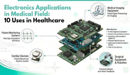
Coverage includes bedside patient monitors, telemetry systems, wearable monitors, and remote patient monitoring devices. They track heart rate, ECG waveforms, respiration, blood pressure, temperature, and oxygen saturation. Hospitals also monitor device status, ward conditions, and medication delivery. Each function needs a healthcare monitoring device PCB matched to its accuracy target.
Continuous monitoring can help clinicians identify changes in patient condition earlier and respond based on real-time data. Nurses respond faster because the system flags the change instead of waiting for a scheduled check. A dropout in the signal path removes clinical visibility entirely. That risk sets the reliability bar for medical equipment electronics.
Hospitals run several monitoring categories side by side, each with distinct electronics requirements. Some track patients directly, while others track devices, environments, or medication. The category tells you what the underlying diagnostic medical device PCB must deliver.
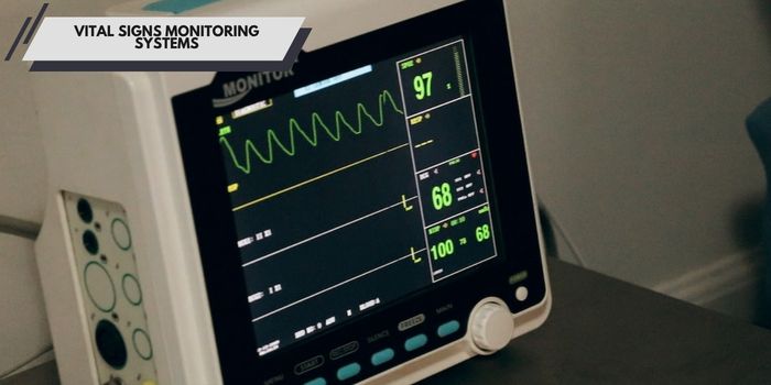
Vital signs monitors capture heart rate, ECG, respiration, blood pressure, temperature, and SpO2 in one unit. The vital signs monitor PCB carries a low-noise analog front end, an isolation barrier, and a display controller. Amplifier stages must resolve microvolt-level cardiac signals. Layout and shielding decisions determine measurement quality.
Remote monitoring moves measurement into the home and streams results to the care team. Cuffs, patches, and pulse oximeters transmit over Bluetooth Low Energy or cellular links. Remote patient monitoring electronics must run for days on a small battery. Power management and RF performance dominate the requirements.
These systems watch the equipment rather than the patient. Ventilators, infusion pumps, and dialysis machines report status, alarms, and service intervals. Biomedical teams use that data to schedule maintenance before a failure. Long service life makes component selection critical.
Ward monitoring tracks temperature, humidity, differential pressure, and oxygen levels in clinical spaces. Operating rooms, isolation rooms, and pharmacy refrigerators all fall under this category. Boards run continuously for years with no service access. Stable laminates and protective coatings keep sensor drift low.

Hospital information systems merge monitoring data with the electronic medical record. They handle admissions, orders, results, and billing in one platform. Monitoring devices feed them through wired or wireless gateways. Gateway hardware needs reliable network interfaces and secure storage.
Medication monitoring covers smart pumps, dispensing cabinets, and barcode verification at the bedside. These systems confirm the right drug, dose, and timing before delivery. Motor drivers, load cells, and scanners all connect to one control board.
Infection surveillance tracks hygiene compliance, sterilization cycles, infection rates, and pathogen test results. Sensor nodes and RFID readers gather events across the facility. Sterilizer monitors survive repeated heat and humidity cycles.
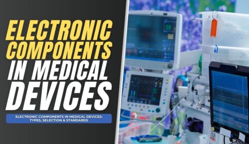
A monitoring framework moves data from the patient to thTo ensure long-term stability and regulatory compliance, selecting the right electronic components in medical devices is critical for patient monitoring components. PCBA quality determines how well the whole chain performs.
Sensors convert physiological activity into electrical signals. ECG electrodes, photoplethysmography sensors, thermistors, and pressure transducers all appear in monitoring products. Signal levels often sit in the microvolt range, so noise control matters more than raw speed. Patient monitor sensor integration requires clean grounding, guarded traces, and controlled impedance.
Acquisition circuits amplify, filter, and digitize the sensor output. An analog front-end medical PCB pairs instrumentation amplifiers with high-resolution ADCs, behind an isolation barrier that limits patient leakage current. Transmission stages then move data over Ethernet, Wi-Fi, BLE, or cellular. A medical telemetry PCB needs controlled impedance routing and defined antenna keep-out zones.
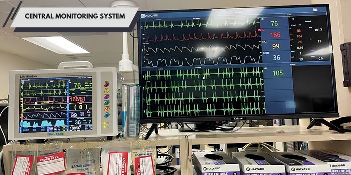
The central system aggregates feeds from many bedside units into one display. Server and gateway boards handle high channel counts and continuous uptime. Redundant power inputs and thermal margin keep them running. Build quality here affects an entire ward rather than one patient.
Visualization covers touchscreens, waveform displays, and mobile dashboards. Display driver boards manage backlight control, capacitive touch sensing, and video timing. High layer count boards route dense display buses without crosstalk.

Storage retains waveforms, trends, and alarm history for review and regulatory audit. Local memory buffers data when the network drops. Solid-state storage and eMMC devices may be integrated on the main controller board.
Alarm circuits drive audible tones, visual indicators, and remote notifications. IEC 60601-1-8 defines alarm priority, tone patterns, and volume behavior. Alarm circuits should be designed so that required alarm conditions remain detectable under defined fault conditions. Functional testing verifies every alarm state before shipment.
Remote access lets specialists review patient data from outside the hospital. Secure gateways handle encryption, authentication, and audit logging. Hardware security modules and secure elements mount on the communication board. Fine-pitch assembly keeps these dense modules within the footprint.
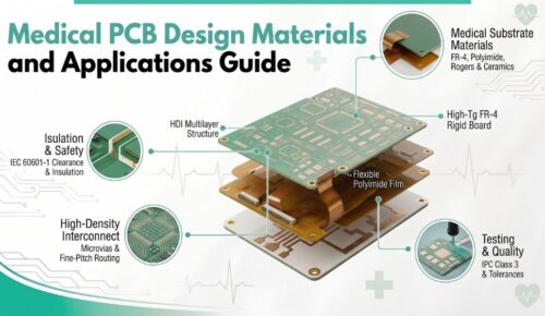
Monitoring hardware uses several board constructions depending on size, signal type, and mechanical fit. Material choice and stackup control measurement accuracy and service life.

Multilayer boards give you dedicated ground and power planes, which cut noise in sensitive measurement circuits. Four to twelve layers cover most bedside and diagnostic products. Separate analog and digital planes keep switching noise away from amplifier inputs. An ECG machine circuit board relies on that plane discipline to resolve small cardiac signals.
HDI construction uses microvias, blind and buried vias, and fine line widths to shrink board area. Wearables, handheld diagnostics, and probe electronics need that density. An HDI PCB medical monitor build routes high-pin-count processors without adding layers. We control via fill and plating to maintain reliability through thermal cycling.

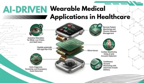
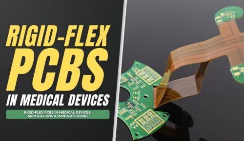
Flex circuits bend to fit curved housings and moving assemblies. Rigid-flex PCB patient monitoring builds combine rigid sections for components with flexible sections for interconnects. You eliminate cable harnesses and the connectors that fail with them. Wearable medical monitor components benefit most from this construction.
Wireless monitoring links need substrates with a stable dielectric constant and low loss tangent. Rogers and PTFE-based laminates can provide stable dielectric properties and low loss for RF and wireless circuits where standard FR-4 is not suitable. Telemetry transmitters, BLE modules, and cellular radios all use them. Consistent dielectric thickness keeps antenna tuning repeatable across production lots.
High-Tg laminates provide higher glass-transition temperatures than standard FR-4, which can improve dimensional stability during demanding thermal processing and cycling. Polyimide reaches higher still for sterilizer and autoclave-adjacent electronics. Higher Tg also improves resistance to via cracking during thermal cycling.
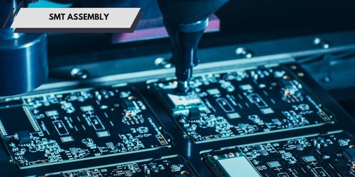
Surface mount assembly places components down to 0201 and 01005 sizes with automated optical alignment. Monitoring boards carry dense passive counts around analog front ends and power stages. We control stencil design, paste volume, and reflow profile for each build. Verified profiles protect temperature-sensitive medical-grade electronic components.

Through-hole parts still appear where mechanical strength matters. Power connectors, transformers, isolation devices, and patient cable receptacles all take mechanical load. Selective soldering places these without exposing nearby SMT parts to extra heat. Hand soldering follows IPC-A-610 acceptance criteria where automation cannot reach.
Monitoring processors, FPGAs, and wireless modules arrive in BGA, QFN, and LGA packages. A medical MCU circuit board often carries several of them in a small area. We place these with automated vision alignment and verify every joint by X-ray. Void percentage and joint shape stay within IPC limits.
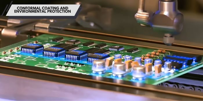
Conformal coating can protect PCB assemblies from moisture, contaminants, and selected chemical exposure when the coating material is matched to the application. We apply acrylic, urethane, silicone, and parylene depending on your requirements. Parylene gives the thinnest uniform layer for wearables and sensor assemblies. UV cure inspection confirms full coverage before final assembly.
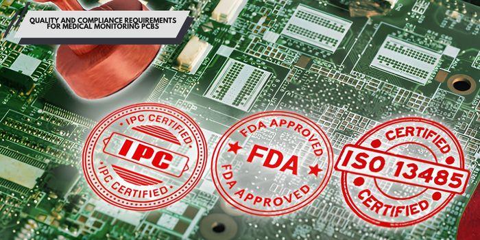
Medical monitoring hardware answers to safety standards, workmanship classes, and quality system rules at once.
IEC 60601-1 sets safety and essential performance rules for medical electrical equipment. For boards, it governs creepage and clearance distances, insulation coordination, and leakage current limits. Patient-connected circuits require defined isolation barriers between applied parts and mains circuits. Hipot testing verifies barrier integrity before shipment.
IPC-A-610 defines three workmanship classes. Class 2 suits dedicated service equipment with normal uptime expectations. IPC Class 3 medical monitoring applies where continued performance is critical, and downtime is unacceptable, tightening annular ring, plating thickness, and solder joint criteria.
ISO 13485 is the international quality management standard for medical device manufacturing. It requires documented processes, risk management, change control, and full record retention. Our ISO 13485 medical PCBA workflow controls every step from incoming inspection to final shipment.
Traceability links every board to its material lot, component date codes, operator, and process parameters. You receive test records, inspection reports, and certificates of conformance with each shipment. Component-level traceability supports recall containment if a supplier issue appears. Controlled sourcing keeps counterfeit parts out of the build.
Inspection catches defects at the earliest point, where correction costs the least. Coverage scales with the class and criticality of your product.
Solder paste inspection measures paste deposits before component placement. The 3D system checks volume, height, area, and offset on every pad. Most solder defects start with incorrect paste, so this step prevents problems downstream.
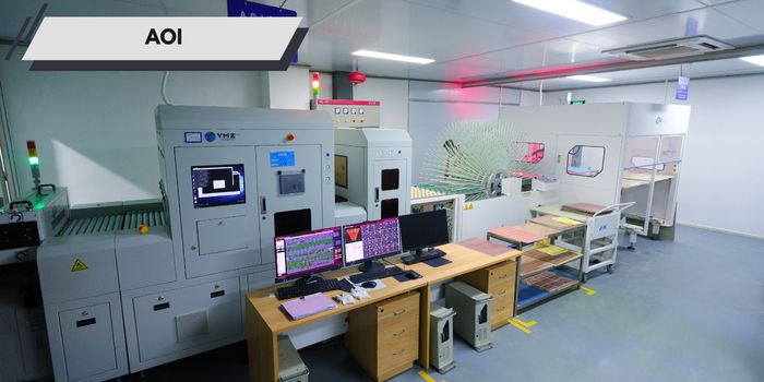
Automated optical inspection checks boards after placement and again after reflow. Cameras verify component presence, orientation, polarity, part markings, and solder fillet shape. High-resolution imaging catches tombstoning, bridging, and insufficient solder.
X-ray inspection reveals joints that optical systems cannot see. BGA, QFN, and LGA packages hide their connections under the body. The system measures void percentage, ball shape, alignment, and head-in-pillow defects. Every Class 3 build with hidden joints gets X-ray inspection.

Electrical testing confirms the board matches its netlist. Flying probe suits prototypes without fixture cost, while in-circuit testing covers volume production. Functional testing powers the board and exercises its real operation, including sensor channels and alarm outputs. A pulse oximeter circuit board gets its LED drive and photodiode path verified under load.
Ionic residue causes corrosion and leakage over time, which shows up as drift in measurement circuits. We test cleanliness to IPC-J-STD-001 requirements using solvent extract resistivity or ion chromatography. Trained operators perform final visual inspection against IPC-A-610 criteria.
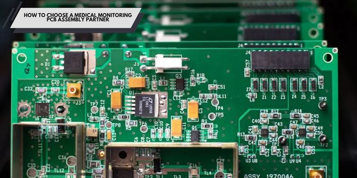
Your supplier choice affects regulatory risk as much as unit cost. Evaluate quality systems, technical capability, and test coverage together.
Confirm current ISO 13485 certification and read the scope statement. Verify FDA establishment registration if you ship into the United States. Check whether the supplier handles change control and deviation reporting formally.
Match capability to your actual board requirements. Ask about maximum layer count, minimum trace and space, HDI microvia capability, and rigid-flex experience. Confirm they place your finest pitch BGAs in production, not just in samples. A blood pressure monitor PCB and a continuous glucose monitor PCB need different capability sets.
Ask which inspection steps run on every board versus by sample. Confirm SPI, AOI, and X-ray availability in-house rather than through subcontract. Review traceability depth, ideally down to component lot and date code. Clear records shorten your own regulatory review cycle.
Choose a partner who runs prototypes and volume on the same documented process. Process changes between phases invalidate your earlier verification data. Ask about turn times, DFM feedback on your documentation, and component procurement support. Consistency across phases protects your validation work.

MedPCB specializes in PCB manufacturing and assembly for medical electronics, supporting OEMs from prototype through volume production. Our ISO 13485 certification sits alongside ISO 9001, UL, RoHS, and REACH compliance. That scope covers patient monitoring components, PCBA, and bedside monitor PCB fabrication, from prototype panels through validated production builds. Our main capabilities in PCB manufacturing:
Ready to start your next medical monitoring device circuit board project? Send us your Gerber files, and we will return a project review and quote.
Yes. HDI construction fits high pin count processors and dense sensor circuits into small housings. Wearable monitors, handheld diagnostics, and compact telemetry units all use it.
Yes. These boards conform to curved housings and moving parts without cables. Polyimide substrates handle repeated bending and sterilization exposure. Removing connectors also removes a common failure point.
Usually yes for patient-critical devices. Class 3 applies where continued performance is essential, and failure carries clinical risk. Your risk assessment and intended use determine the class.
High-Tg FR-4 covers most builds. Polyimide serves flex sections and high-temperature areas. Low-loss laminates such as Rogers handle wireless telemetry stages. Operating temperature and sterilization method drive the choice.
Medical monitoring hardware only performs as well as the board underneath it. Construction, material selection, assembly control, and inspection coverage all shape clinical reliability. Choose a partner who works only in medical electronics and documents every step.


Hello, I am Sony He, with extensive practical experience in medical PCB and PCBA manufacturing. Over the years, I have focused on medical circuit board manufacturing, rigid-flex PCB, SMT assembly, quality inspection and reliability compliance. I enjoy sharing hands-on expertise in medical PCB manufacturing and assembly through technical articles.




English

French

German

Japanese

Korean


