

PCB Materials for Long-Term Reliability in Implantable Patient Monitoring Devices
-

-
September 09, 2026


An implantable patient monitor operates for 10 to 15 years without maintenance access, and its material set determines whether it reaches that mark. Substrate, conductor finish, and encapsulation each carry part of that burden. This guide reviews the materials that perform reliably in that environment and the fabrication controls that support them.
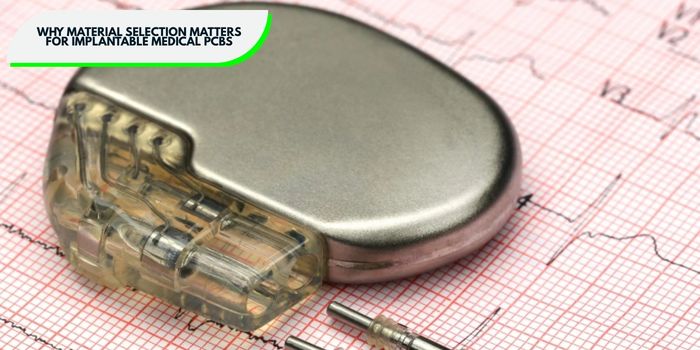
Material selection has a direct impact on the long-term reliability of implantable medical PCBs. These devices must operate for years in a tightly controlled environment while maintaining stable electrical and mechanical performance. The substrate, conductor system, and protective materials must therefore withstand moisture exposure, temperature changes, mechanical stress, and the intended sterilization or packaging process. Selecting suitable materials early helps your project reduce the risk of corrosion, delamination, insulation failure, and other reliability problems during the device’s service life.
Implantable devices may remain in service for many years with limited or no access for maintenance. Materials therefore need sufficient long-term stability for the intended application, supported by appropriate material characterization, aging data, and device-level validation. IPC Class 3 requirements may also be specified for high-reliability PCB fabrication, depending on the device and your requirements.
Moisture and ionic contaminants can contribute to corrosion, leakage current, and insulation degradation if they reach exposed conductors. Implantable electronics therefore require appropriate substrate, conductor, coating, and packaging choices to limit moisture and chemical exposure. Depending on the device design, protective barriers may include conformal coatings, encapsulation, or hermetic packaging.
Constant biomechanical motion forces implantable PCBs to bend thousands of times a day, causing standard rigid laminates to rapidly fail from mechanical fatigue. Polyimide PCB medical implants take the strain instead. For medical devices, thermal stress peaks during assembly (reflow) and preparation (sterilization), not during operation. High-Tg PCB laminates are essential to preserve dimensional stability and board integrity through these intense, high-heat processes.
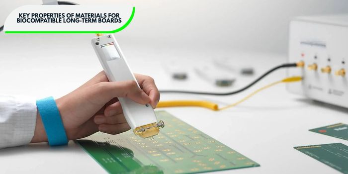
Laminates designed for IPC Class 3 medical applications require biocompatibility, corrosion resistance, thermal stability, mechanical durability, and electrical stability. A flaw in any single property compromises the entire board.
The substance must cause no toxic, inflammatory, or sensitizing reaction in surrounding tissue. ISO 10993 defines the test series, and it applies to every substrate, finish, and coating in the stack rather than only the outer surface.
Bodily fluids corrode standard laminate and bare copper. Water absorption and residual ionic contamination are two key metrics used to evaluate corrosion risk, and both require explicit limits on the fabrication drawing.
A high-Tg medical PCB laminate maintains dimensional stability through both thermal events, preserving board integrity throughout fabrication and assembly.
Body movement applies repeated bending that cracks rigid laminate and separates layers. Peel strength and delamination resistance describe durability here more accurately than tensile figures.
Monitoring accuracy depends on impedance that stays stable across the full service life. Target impedance of 50 ohms within 5%, with dielectric loss low enough to maintain signal integrity at the operating frequency.
Every material balances cost, flexibility, and barrier performance. Use the reference data below to shortlist candidate materials before choosing.
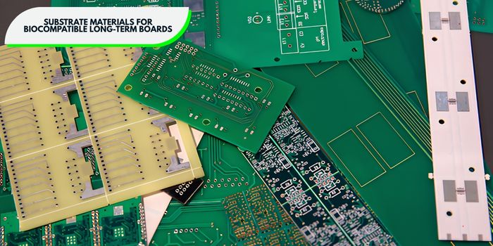
The substrate is the foundation, and thickness, bending behavior, moisture uptake, and temperature ceiling all follow from it. Implant location and expected service duration should drive the choice.
Copper traces corrode quickly once moisture and salts reach them, so on corrosion-resistant boards the surface finish carries the protection. Deposit thickness and porosity control influence the result as much as the metal itself, and both belong on the drawing.
Gold-plated traces remain the standard for balancing cost against service life. Verify plating thickness by cross-section on production coupons.

Encapsulation is the last barrier between the electronics and body chemistry. On an encapsulated component board, it must form a continuous protective barrier without adding bulk or transferring stress into fine-pitch solder joints, and coating uniformity governs the outcome.
Parylene C under silicone is the common production combination, because the first layer closes pinholes and the second absorbs movement. A pinhole at one component edge accounts for more field failures than any other coating defect, so cure schedule, thickness, and coverage all require process control rather than sample inspection.
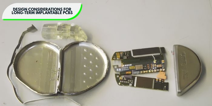
Implantable monitors carry sensors, power, and data links inside a very small volume, so high-density construction becomes unavoidable. Process capability, not preference, sets the limits described below. Confirm each one with your manufacturing partner before you release files for medical device PCB fabrication.
Polyimide layers as thin as 0.05 mm let you tighten trace and via spacing, which supports genuinely dense layouts in a small footprint. Handling difficulty rises sharply as thickness falls. Panel warp, registration drift, and via cracking all increase along with it. Ask your fabricator which core thickness they run in volume production, since that figure usually differs from the thinnest material they have processed on a trial basis.
Gold-plated traces down to 0.075 mm width hold reliable connections in confined spaces. Etch tolerance starts to govern yield below that geometry. Copper weight and line width also constrain each other once you introduce impedance control.
Builds of 6 to 10 layers handle complex routing while keeping the form factor small enough for implantation. Every added layer brings another lamination cycle and another opportunity for delamination. Balance the stackup as well, because an unbalanced build will not emerge flat from lamination.
Barrel plating thickness, aspect ratio, and copper ductility together determine how long they last. Keep the aspect ratio conservative as cores get thinner. Filled and capped vias also close off moisture paths through the board. Coupon sections from each panel confirm barrel integrity before assembly begins.
Lock down minimum trace and space, minimum drill diameter, layer count, material lead time, and coating keep-out zones before the layout freezes. Any late change to those items forces a requalification. Material availability carries the largest schedule risk, since specialty polyimide and LCP stock often runs long lead times.
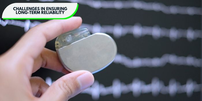
Material selection and process control must guard against moisture ingress, electrochemical migration, fatigue, and signal degradation.
Body fluid penetrates gaps far smaller than anything visible under inspection, and corrosion or short circuits follow. Water vapor also diffuses directly through polymer coatings without any gap at all. Parylene C encapsulation minimizes both paths by forming a uniform, pinhole-free barrier.
Ionic residue, moisture, and applied bias together grow conductive paths between adjacent conductors. CAF follows the lowest resistance route, which runs along glass fiber bundles inside reinforced laminate. Non-reinforced substrates such as polyimide and LCP eliminate the glass-weave migration pathway entirely. Tight ionic cleanliness limits eliminate the remaining driver, so verify cleanliness after every wash cycle rather than at final inspection.
Repeated mechanical stress from body movement cracks copper conductors and opens the weakest bond line. Flexible substrates such as polyimide absorb that stress far better than rigid alternatives. Adhesiveless construction improves matters further by removing the acrylic layer where delamination usually initiates. State minimum peel strength and thermal shock requirements on the print, since both tests expose weak bonds before assembly.
Dielectric properties shift as materials age and absorb moisture, and high-frequency performance follows them down. A 2.4 GHz wireless link shows that drift first, through rising insertion loss and moving impedance. Low-loss dielectrics paired with stable conductive finishes hold performance across the full service interval.

No board enters an implantable device without passing a documented test sequence. Biocompatibility results, active implant compliance, IPC Class 3 workmanship evidence, and aging data form the package a reviewer will examine.
ISO 10993 governs biological evaluation for any material that contacts the body, covering cytotoxicity, sensitization, and irritation. Its scope reaches every substrate, finish, and coating in the stack rather than the outer surface alone. Request the full evaluation file from each supplier before you commit to a material.
ISO 14708 sets requirements for active implantable medical devices, including fluid ingress protection, mechanical integrity, and electrical safety. Your board and its encapsulation must support the device-level claims written against those clauses. Map the material file to the relevant sections at program start.
IPC-6012 defines qualification and performance requirements for rigid printed boards, while IPC-6013 covers flexible printed boards and rigid-flex constructions. The applicable IPC performance class and acceptance criteria should be specified according to the board type, application, and customer requirements.
Accelerated aging simulates long-term exposure using elevated heat, humidity, and electrical bias. Arrhenius modeling then converts the test results into a predicted operational lifespan. Sample quantity drives statistical confidence, so plan the population before you start.
Electrical test confirms impedance stability, commonly 50 ohms within 5 percent, along with continuity and isolation. Insulation resistance testing identifies marginal dielectric before the board reaches a patient. Ionic contamination testing detects flux and process residue that would otherwise feed migration years later.
Your sterilization method narrows the acceptable material list immediately. Ethylene oxide, gamma radiation, and steam degrade polymers through different mechanisms. Some epoxies and adhesives yellow, embrittle, or outgas after gamma exposure. Qualify materials against the full expected cycle count, since a single pass demonstrates very little about long-term behavior.
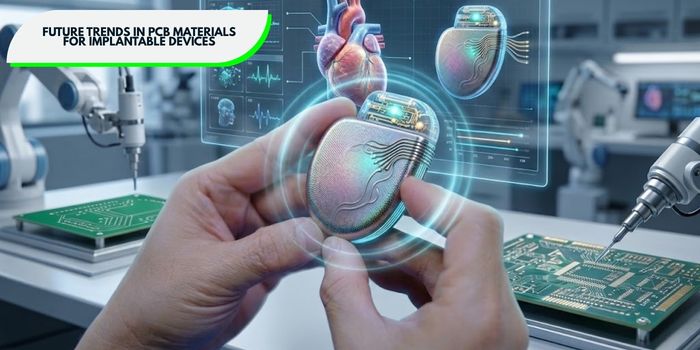
Researchers continue to develop substrates that dissolve harmlessly in the body once the monitoring period ends, which removes the need for surgical retrieval. Magnesium, silicon dioxide, and selected polyesters lead the way.
Nanocoatings applied by atomic layer deposition reach water vapor transmission rates that conventional polymers cannot approach, at thicknesses measured in nanometers. Conductive inks enable finer features on flexible PCB patient monitoring substrates. Both approaches reduce total device thickness while improving corrosion resistance.
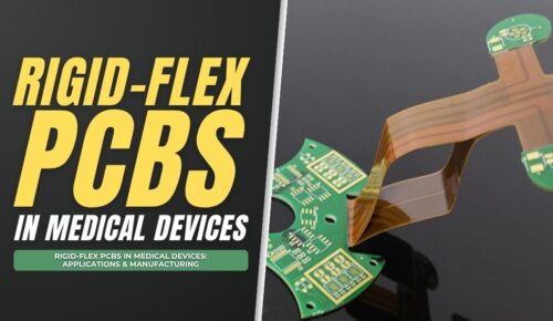
Combining rigid and flexible materials in one board optimizes space and durability for complex monitoring systems. Components mount on rigid islands while interconnects run through flexible sections, which removes internal connectors from the assembly. That change matters, because connectors fail more often than the boards they join. Bend radius and layer count need early coordination with your fabricator.

MedPCB specializes in PCB manufacturing and assembly for medical electronics, supporting OEMs from prototype builds through volume production. Our ISO 13485 certification sits alongside ISO 9001, UL, RoHS, and REACH compliance. You work with one qualified source for fabrication, assembly, and verification.
Ready to start your next project? Send us your Gerber files, and we will return a project review and quote.
Material choices decide whether an implantable monitor performs for fifteen years or fails in two. Polyimide substrates, gold-plated conductors, and Parylene C encapsulation each address a specific failure mechanism inside the body. Confirm every selection through biocompatibility, aging, cleanliness, and electrical testing before production.


Hello, I am Sony He, with extensive practical experience in medical PCB and PCBA manufacturing. Over the years, I have focused on medical circuit board manufacturing, rigid-flex PCB, SMT assembly, quality inspection and reliability compliance. I enjoy sharing hands-on expertise in medical PCB manufacturing and assembly through technical articles.




English

French

German

Japanese

Korean


