

Medical PCB Design Materials and Applications Guide
-

-
October 15, 2026


Medical PCB design requires careful material selection, reliable circuit layouts, and controlled manufacturing processes. For medical device engineers and OEM development teams, these decisions affect signal integrity, electrical safety, miniaturization, and long-term reliability.
This guide covers medical PCB design guidelines, substrate materials, PCB construction types, applications, and manufacturing requirements to help you prepare designs for fabrication and assembly.
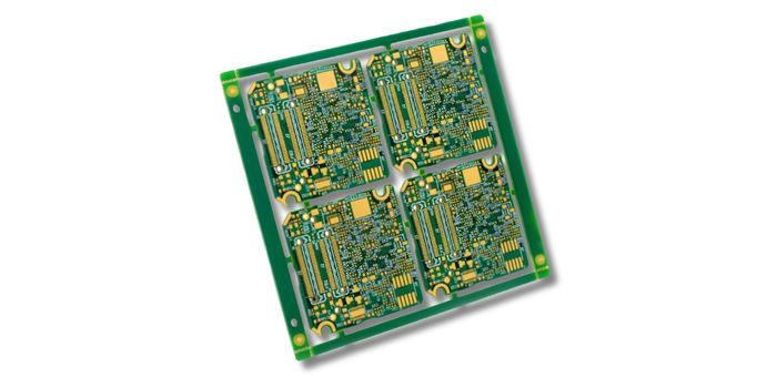
Medical PCBs are used in equipment with demanding requirements for electrical safety, reliability, cleanliness, and manufacturing traceability. Critical applications may specify IPC Class 3 acceptance criteria, tighter process controls, and additional inspection records. These requirements help medical device manufacturers manage quality and production risks.
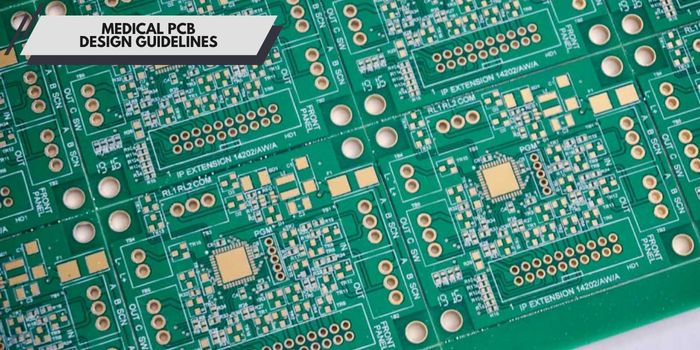
Following established medical layout practices improves fabrication success. Designers must control stack-up, spacing, shielding, and test access before releasing Gerber files. ISO 13485 systems require robust documentation and risk control.
Disciplined stack-up planning reduces board size and improves yield. High-density structures enable miniaturized medical builds.
Controlled impedance routing maintains signal quality in high-speed digital and RF circuits. Designers must define target impedance and tolerances directly on fabrication notes. Route high-speed pairs with consistent spacing and solid reference planes. Minimize stubs, splits, and via transitions on critical nets.
Medical electrical equipment must maintain appropriate insulation between hazardous voltages, accessible circuits, and patient-connected parts. IEC 60601-1 defines electrical safety requirements, including means of protection (MOP), creepage, clearance, and dielectric strength. PCB designers should identify insulation barriers, define creepage and clearance requirements, and document these boundaries in the layout and fabrication drawings.
Solid grounding and shielding control electromagnetic emissions and immunity. Partitioning analog, digital, and RF sections limits crosstalk. Copper planes and thermal vias help spread heat from power components and other localized heat sources. Medical PCBAs require dedicated space for airflow and heatsinks. Sharing hot-stage requirements helps manufacturers select suitable laminates.
Strict design for manufacturing checks increase first-pass yield. Standardizing footprints, solder mask openings, and assembly tolerances prevents production delays. Avoid acid traps, tight annular rings, and untestable nets. A DFM/DFA review before production helps identify fabrication, assembly, and test-access issues.
Substrate selection depends on temperature, frequency, power, and sterilization requirements. Engineers must evaluate electrical performance, thermal stability, mechanical requirements, manufacturing compatibility, and cost. Locking in material choices early prevents requalification delays.
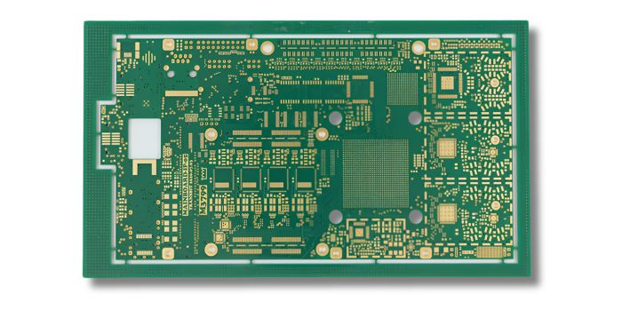
High-Tg FR-4 is widely used in rigid multilayer PCBs for patient monitors, diagnostic equipment, and medical control systems. Compared with standard FR-4, high-Tg laminates offer improved thermal stability during PCB fabrication and lead-free assembly. They also support complex multilayer constructions at a relatively economical cost.
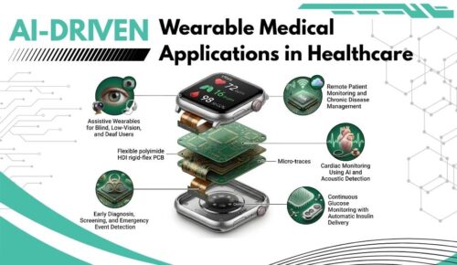
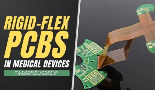
Flexible polyimide films achieve repeated bending for wearables and probes. Rigid-flex constructions reduce internal connector and cable requirements in compact medical devices. Polyimide films provide flexibility, thermal stability, and dimensional performance for flexible and rigid-flex PCB constructions.
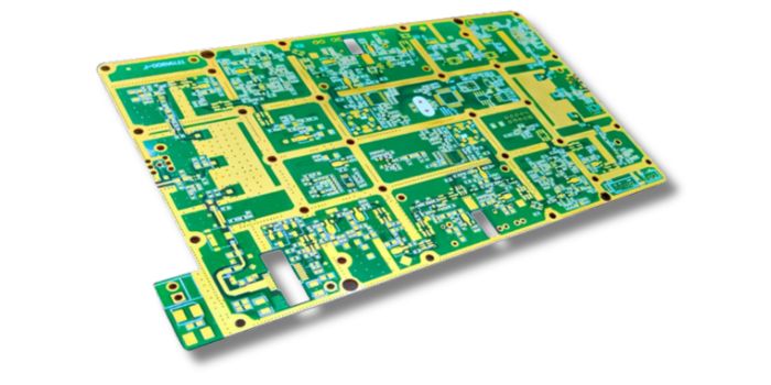
Low-loss RF laminates, including selected Rogers and PTFE-based materials, support high-frequency medical circuits. Their controlled dielectric properties help maintain signal integrity in wireless telemetry, RF sensing, and other high-frequency applications.
Ceramic substrates such as alumina and aluminum nitride offer electrical insulation, dimensional stability, and useful thermal properties for specialized electronic modules. Ceramic substrates are used in selected high-power, high-frequency, and specialized medical electronic modules.
Insulated metal substrate (IMS) PCBs use an aluminum or copper base with a thermally conductive dielectric layer. They provide an effective heat-transfer path for high-power LEDs, power electronics, and selected medical laser systems.
Liquid crystal polymer (LCP) is used in selected flexible circuits and high-frequency electronic structures because of its low moisture absorption and stable electrical properties. PEEK is used in medical device housings, structural components, and electrical insulation.
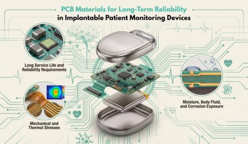
Implantable electronics require device-level evaluation of material biocompatibility, packaging integrity, and long-term reliability.
Construction types vary based on size, movement, density, and power requirements.
Mapping each device to the correct laminate and construction ensures optimal performance. Engineers must weigh power, frequency, size, and patient contact risks. Clear material and test records streamline the final approval process.

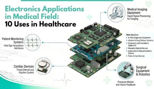
Medical imaging systems use different PCB technologies for signal acquisition, processing, power control, and communication. High-speed multilayer and controlled-impedance PCBs support imaging data transmission, while RF circuits in MRI equipment require careful material selection and signal integrity design.
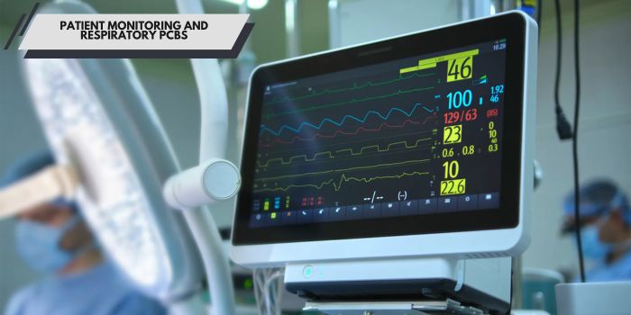
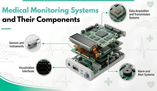
Low-noise monitoring boards keep vital-sign data stable. Blood monitors tracking glucose and SpO2 use specific circuit builds. Ventilators and portable monitors typically utilize rigid multilayers or rigid-flex construction.
Implantable cardiac and neurostimulation devices use compact electronic assemblies, specialized interconnects, and protective packaging to support long-term operation. Neurostimulators depend on hermetic micro-assembly. Hearing aids demand microvias and fine lines to fit inside tiny modules.
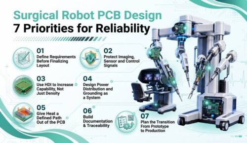
Rigid-flex builds drive precise motion in surgical robots. Metal-core boards cool laser drivers and electrosurgical outputs. Heavy copper and thick plating carry high current safely. Designers must shield sensitive control nets from high-power switching noise.
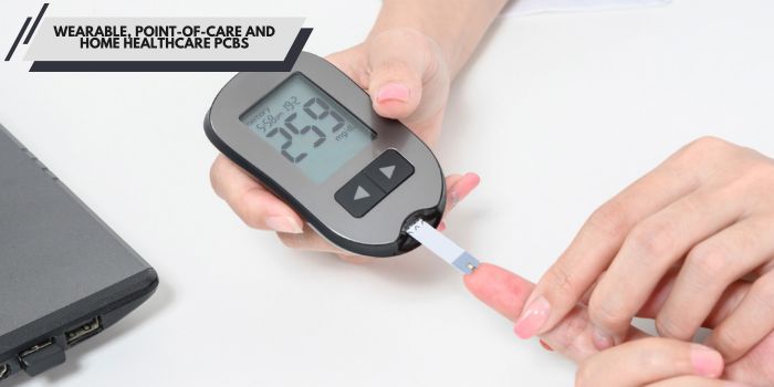
Wearable sensor flex circuits enable patient comfort and mobility. HDI and rigid-flex construction shrink readers and patches. Low-power component selection and power management help extend battery life. Wireless links support remote monitoring and home diagnostics.
Stable infusion pump control boards deliver accurate dosing. Compact multilayer assemblies combine sensors, motors, and alarms. Strict cleaning and conformal coating prevent corrosion. Traceability for each lot supports recalls and audits.

Converting approved files into reliable assemblies requires controlled fabrication and testing. Clean soldering, verified inspection, and complete records guarantee success for every lot.
Automated SMT lines place miniature sensors and ICs accurately. Controlled reflow profiles help achieve reliable solder joints while maintaining component and PCB thermal limits. Combining SMT with through-hole techniques supports connectors and high-current joints. Manufacturing records track PCB batches, component lots, assembly processes, and inspection results.
Comprehensive testing protocols catch defects early and verify critical performance before any board ships.
Cleaning and contamination-control processes reduce flux residues and ionic contamination on medical PCB assemblies. Cleanliness verification supports process control and product reliability.
Conformal coating provides additional environmental protection against moisture and contaminants. Connectors, test points, and other designated areas must be masked before coating.

Medical manufacturers operate under ISO 13485 quality systems. PCB manufacturers support these systems through documented processes, material traceability, inspection records, and change control.
Rigid PCB acceptance follows IPC-6012 and IPC-A-600; assembly and soldering use IPC J-STD-001 and IPC-A-610. IPC Class 3 is used for high-reliability applications per customer specifications.
IEC 60601-1 and IEC 60601-1-2 set safety and EMC rules for finished medical devices, assessed at the equipment level.
Following these specifications reduces compliance risks and speeds up your medical device certification.
MedPCB operates as a fully certified, one-stop medical PCB and PCBA manufacturer. Our facilities specialize in high-density HDI circuits, high-speed and high-frequency medical boards, and ultra-fine pitch precision SMT assembly. All medical production strictly complies with ISO 13485 quality systems and meets IPC Class 2 and Class 3 reliability standards to support diagnostic, wearable, implantable, and life-support devices.
Submit your Gerber files and BOM today to receive a professional DFM review and an accurate project quote from a reliable, high-grade medical electronics manufacturing partner.
Use flex circuits for bending movement in wearables and probes. Choose rigid-flex for sealed devices needing fewer internal connectors. Apply HDI for dense processors in imaging equipment. Rigid-flex HDI combines flexible interconnections with high-density routing for compact medical electronics.
Implantable electronics use specialized polymers, ceramics, metals, and protective packaging materials. Biocompatibility is evaluated according to the finished device’s contact conditions and applicable ISO 10993 requirements. Material selection alone does not establish implantable device safety.
ISO 13485 controls the overall device quality system rather than just the board etching process. Engineers own the design history, risk management, and supplier oversight. Fabricators provide the necessary records, inspection data, and process controls for audits.
IPC Class 3 defines high-reliability acceptance requirements within applicable IPC standards. IPC-6012EM addresses additional performance requirements for rigid PCBs used in medical equipment. Medical OEMs specify the applicable standard, performance class, and acceptance requirements in their fabrication documentation.
Medical PCBAs undergo inspection and testing using AOI, X-ray, ICT, and functional testing. Bare PCB verification may include electrical testing and microsection analysis. Cleanliness testing, thermal cycling, and environmental testing provide additional manufacturing and reliability data.
Medical PCB design requires careful coordination between material selection, circuit layout, manufacturing, and testing. Clear fabrication requirements and early DFM/DFA review help medical device engineers improve manufacturability and maintain consistent production quality.


Hello, I am Sony He, with extensive practical experience in medical PCB and PCBA manufacturing. Over the years, I have focused on medical circuit board manufacturing, rigid-flex PCB, SMT assembly, quality inspection and reliability compliance. I enjoy sharing hands-on expertise in medical PCB manufacturing and assembly through technical articles.




English

French

German

Japanese

Korean


